


The survey methods on bare-liners or exposed geomembranes are the fastest and quickest in terms of coverage and time when compared to other surveys. Setup is minimal and preparations are simple. These methods are highly accurate, and when leaks are detected, they are marked immediately during the survey process.
NOTE: Bare-Liner Surveys using a variety of leak detection methods are typically performed on single geomembrane liner systems. However, geosynthetic applications with double geomembrane liner systems can also be serviced using these methods. The top-most, relative geomembrane liner must contain a conductive medium directly underneath the liner. Leaks that are present in double-lined systems with non-conductive geotextile, geonet, geogrid, or geocomposite can be detected and located, if and only if, there is a continuous electrical connection through both geomembrane liner systems.
APPLICABLE ASTM STANDARDS
- ASTM D6747-15 - Selection of Techniques for Electrical Leak Location of Leaks in Geomembranes
- ASTM D7002-16 - Electrical Leak Location on Exposed Geomembranes Using the Water Puddle Method
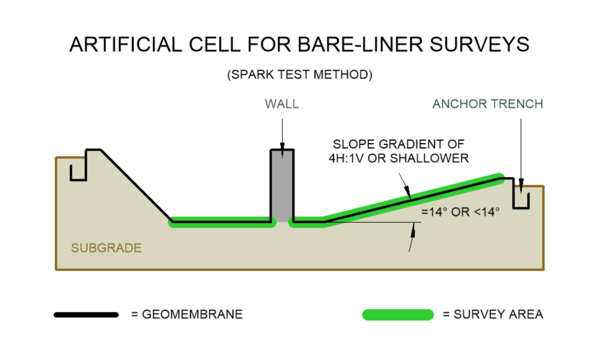
- ASTM D7240-06 - Leak Location using Geomembranes with an Insulating Layer in Intimate Contact with a Conductive Layer via Electrical Capacitance Technique (Conductive Geomembrane Spark Test)
- ASTM D7953-14 - Electrical Leak Location on Exposed Geomembranes Using the Arc Testing Method

Click to view >

Featured Project

BEST IN BARE-LINER SURVEYS
"Most Popular Survey Method"
"Most Leaks Located Per Area"
"Fastest Survey Area Coverage"
"Ranks Highest In Leak Detection
Sensitivity"
Water Puddle Conventional
Service ID
D7002 - PUDC
COVERAGE
DESCRIPTION
REQUIREMENTS
DOWNLOADS
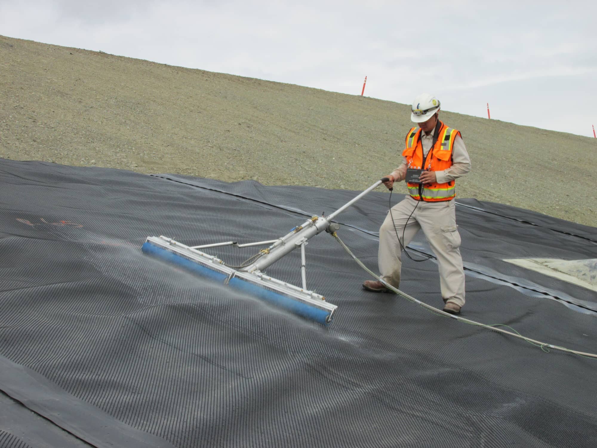
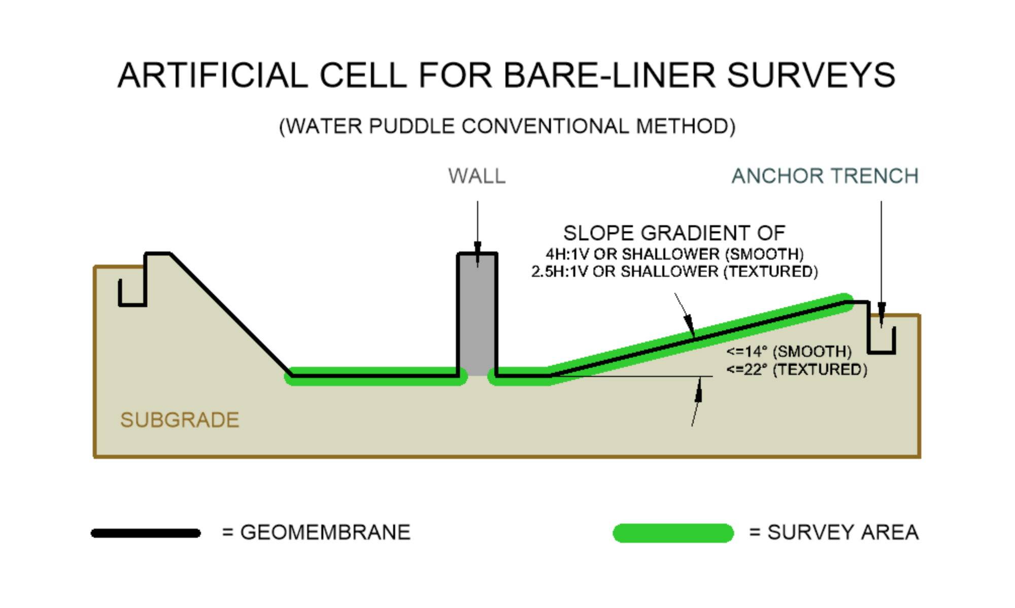
Floor areas, smooth side slopes with a slight inclined plane angle of 14° or less (slope gradient of 4H:1V or shallower), or textured side slopes with a slight inclined plane angle of 22° or less (slope gradient of 2.5H:1V or shallower)
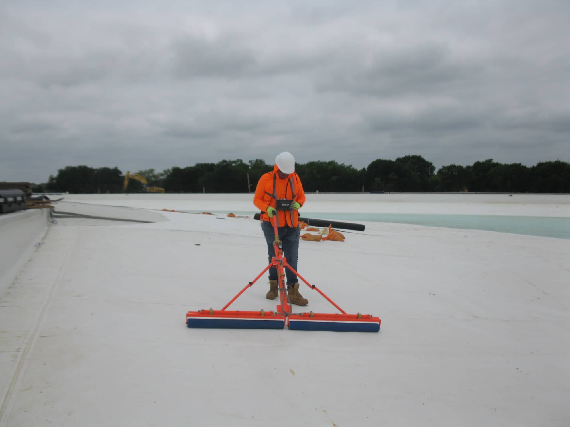
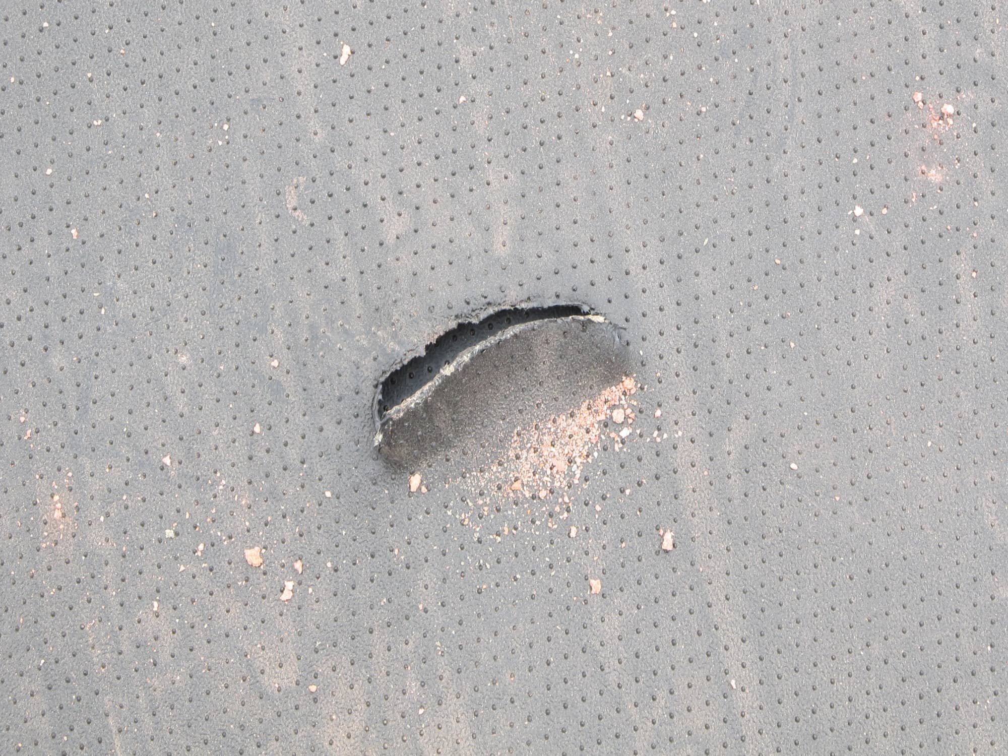
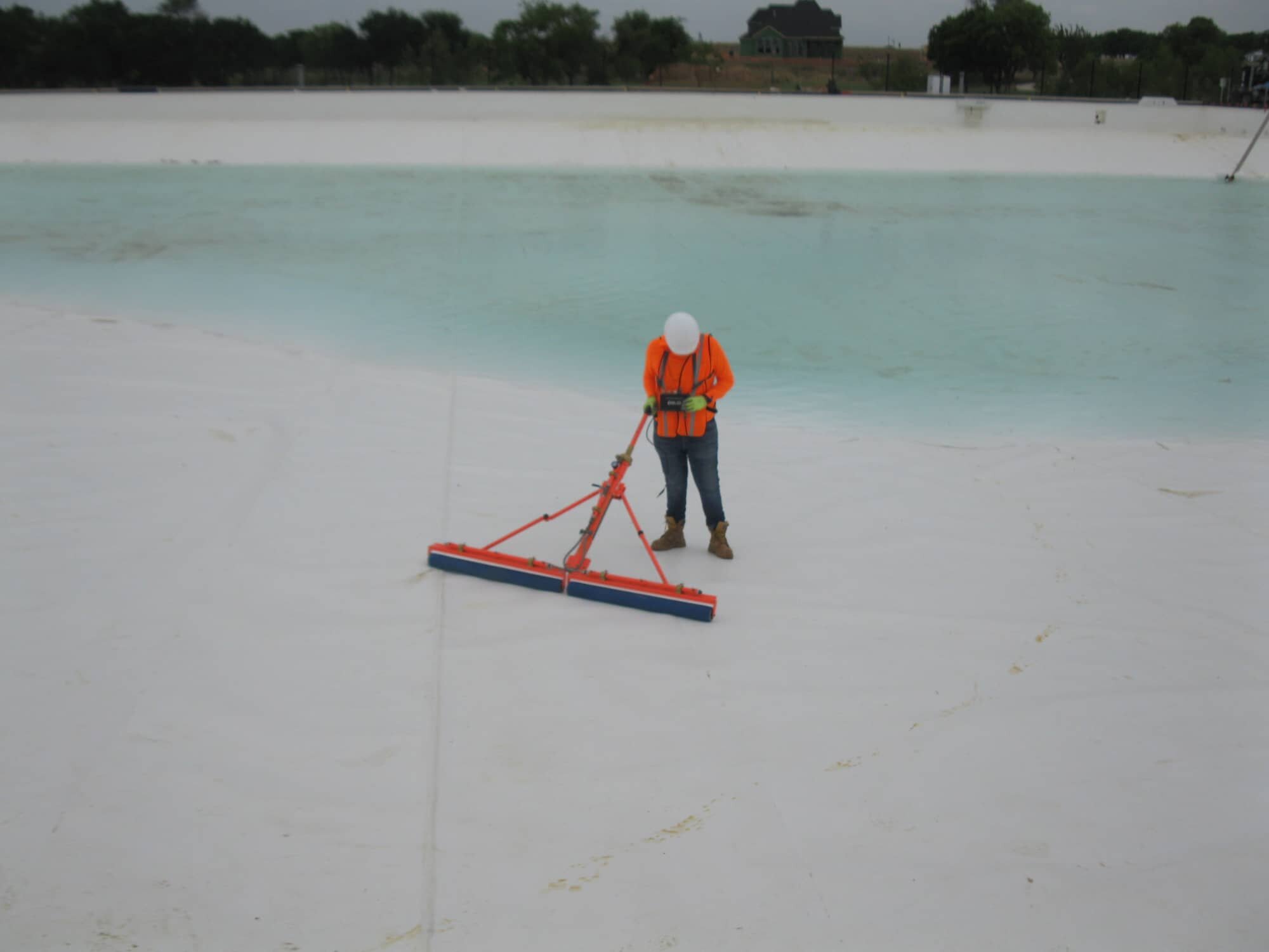
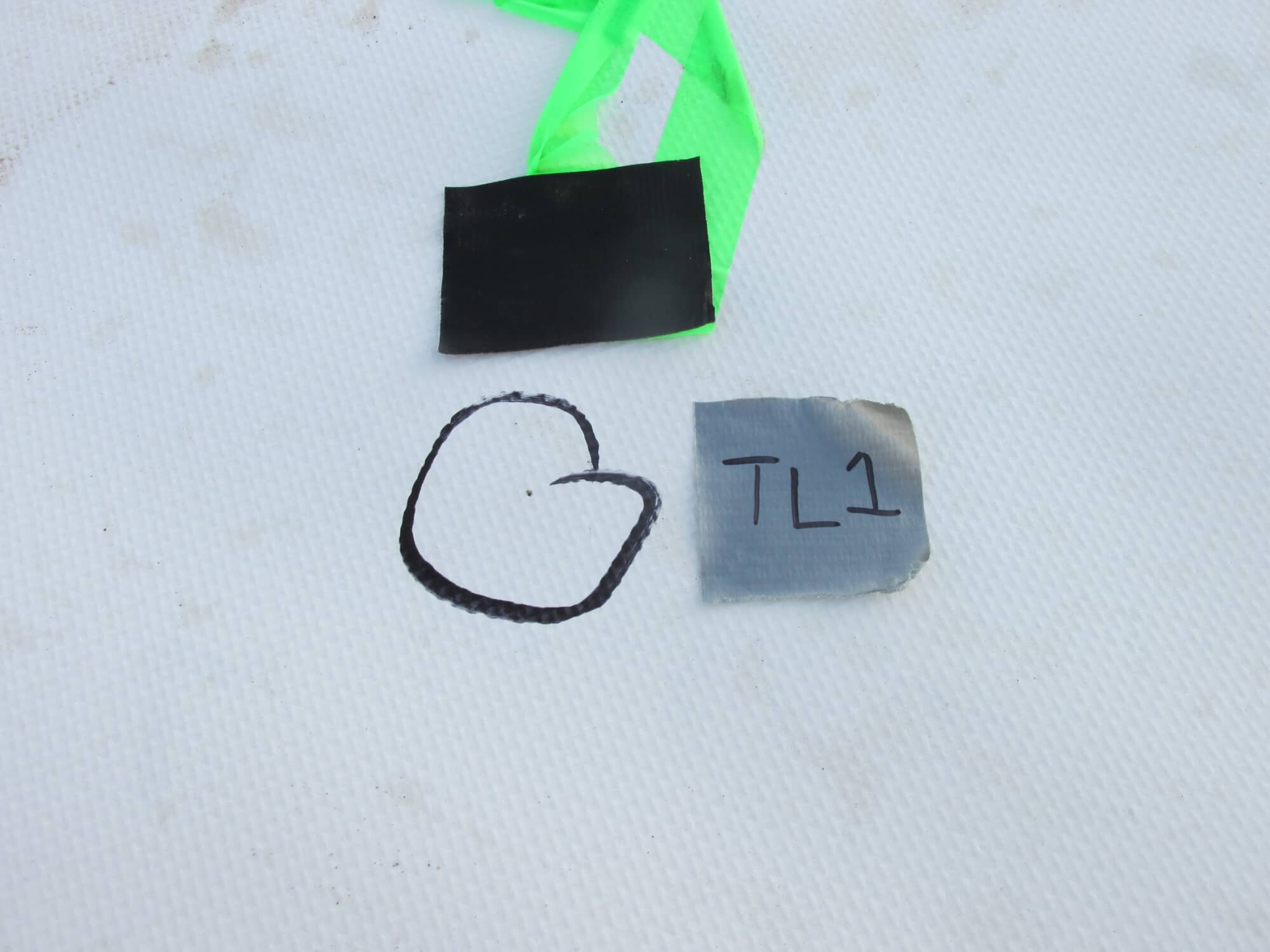
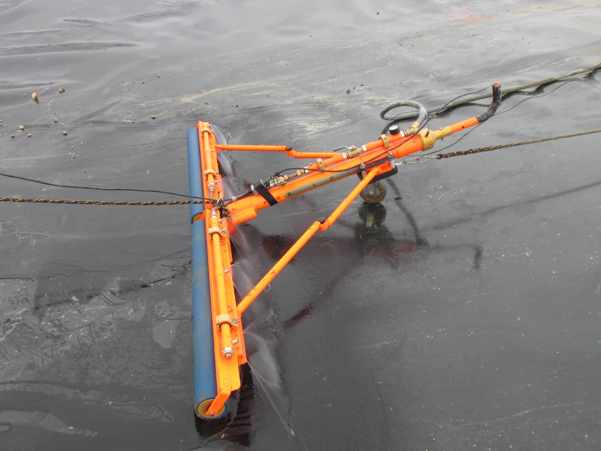
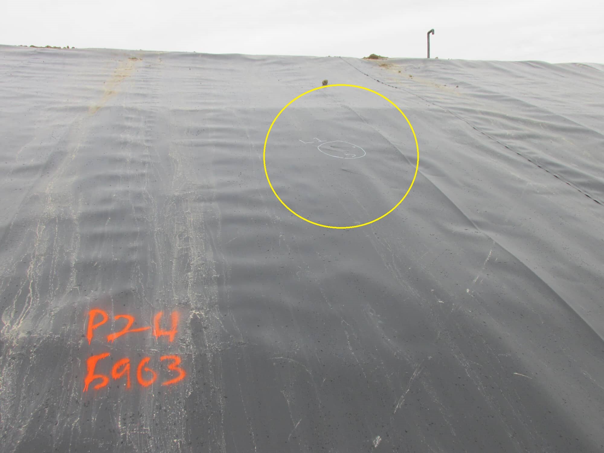
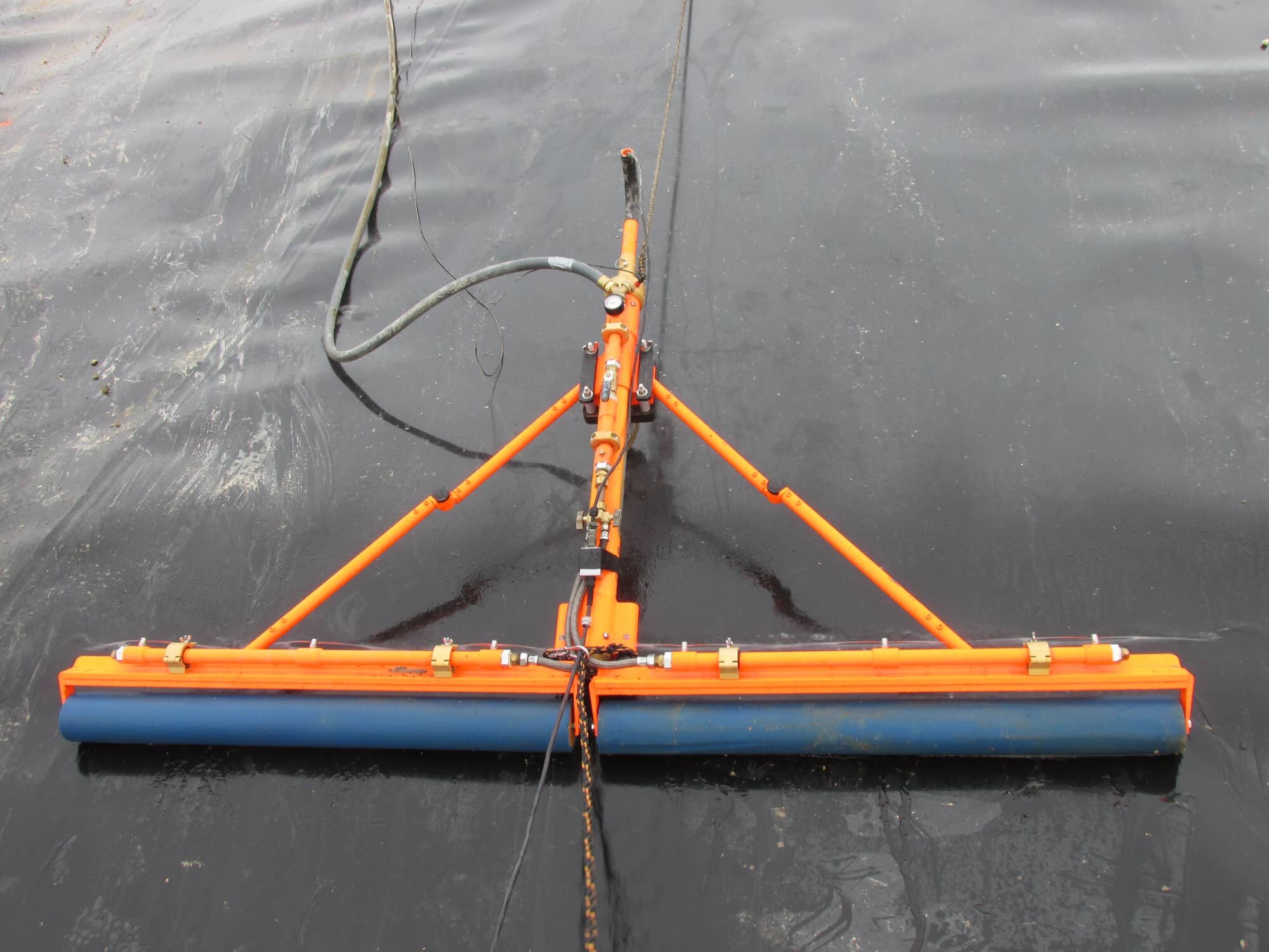
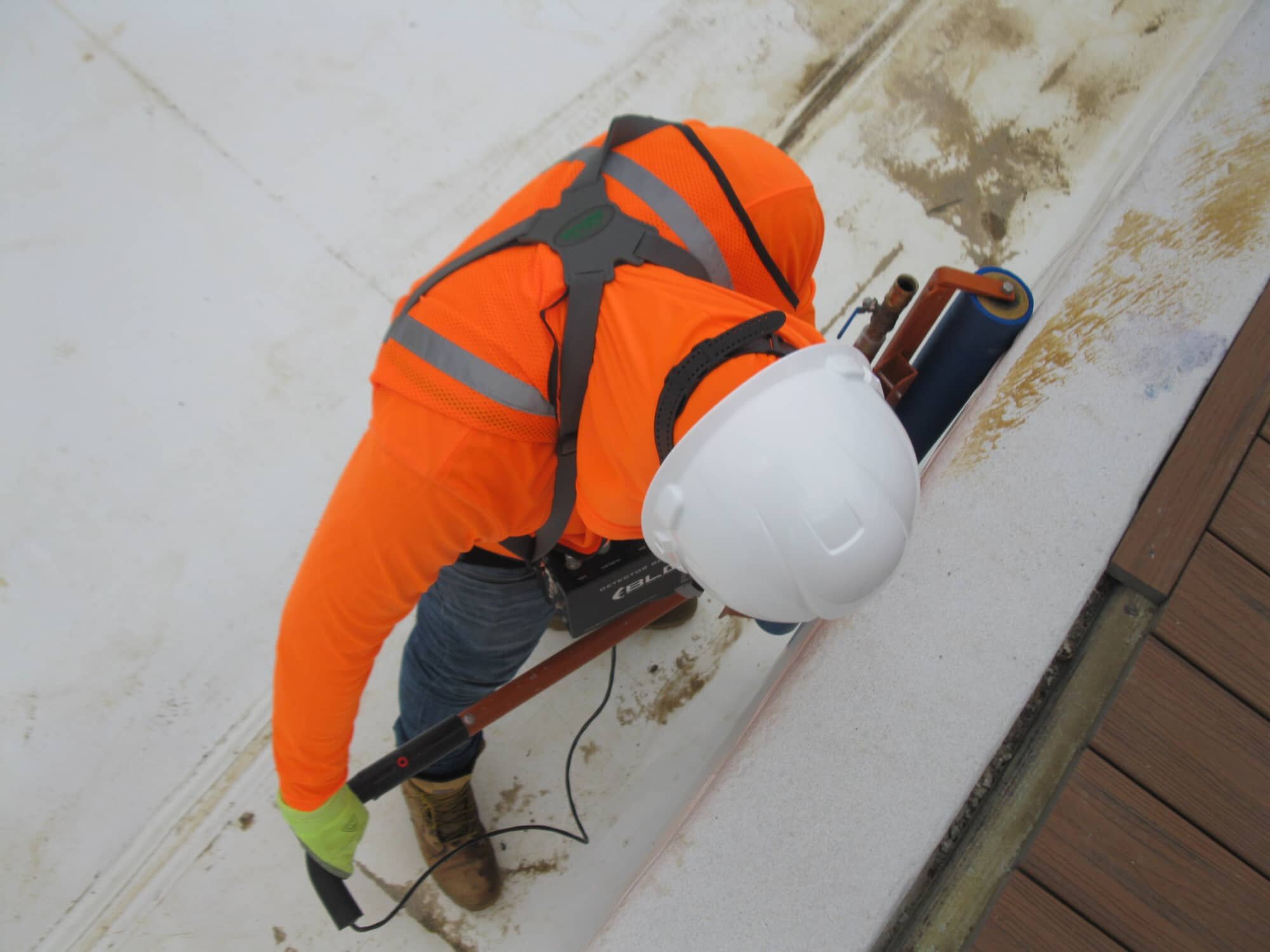
The Water Puddle Conventional Method is, by far, the mostly preferred method when it comes to bare-liners. This survey is performed by pushing a probe along the floor area, or in parallel with the face of the slope. The entire floor area is surveyed prior to any surveys along the slope. Once the survey of the floor area is complete, surveying of the slope will begin from the lowest slope elevation. The technician will push the probe in parallel along the slope and progressively increment to the next survey line until the slopes are complete. When a penetration, defect, or damage on the geomembrane is encountered, the water sprayed from the probe completes a circuit. This connection, or electrical continuity, is translated through a leak detector box and a high frequency audible tone is generated to alarm the technician.
(280 kPa)
approximately 100 ft (30 m)
See our Preparations and Requirements Guide for General Contractors prior to an on-site leak detection service.

PREP Guide Single-Lined Systems

PREP Guide Double-Lined Systems
Click to view our Specifications Guide for the Electrical Leak Detection Quality Assurance Program using this method.

SPEC Guide Single-Lined Systems

SPEC Guide Double-Lined Systems

Service ID
D7002 - PUDS
Water Puddle Slope
COVERAGE
DESCRIPTION
REQUIREMENTS
DOWNLOADS
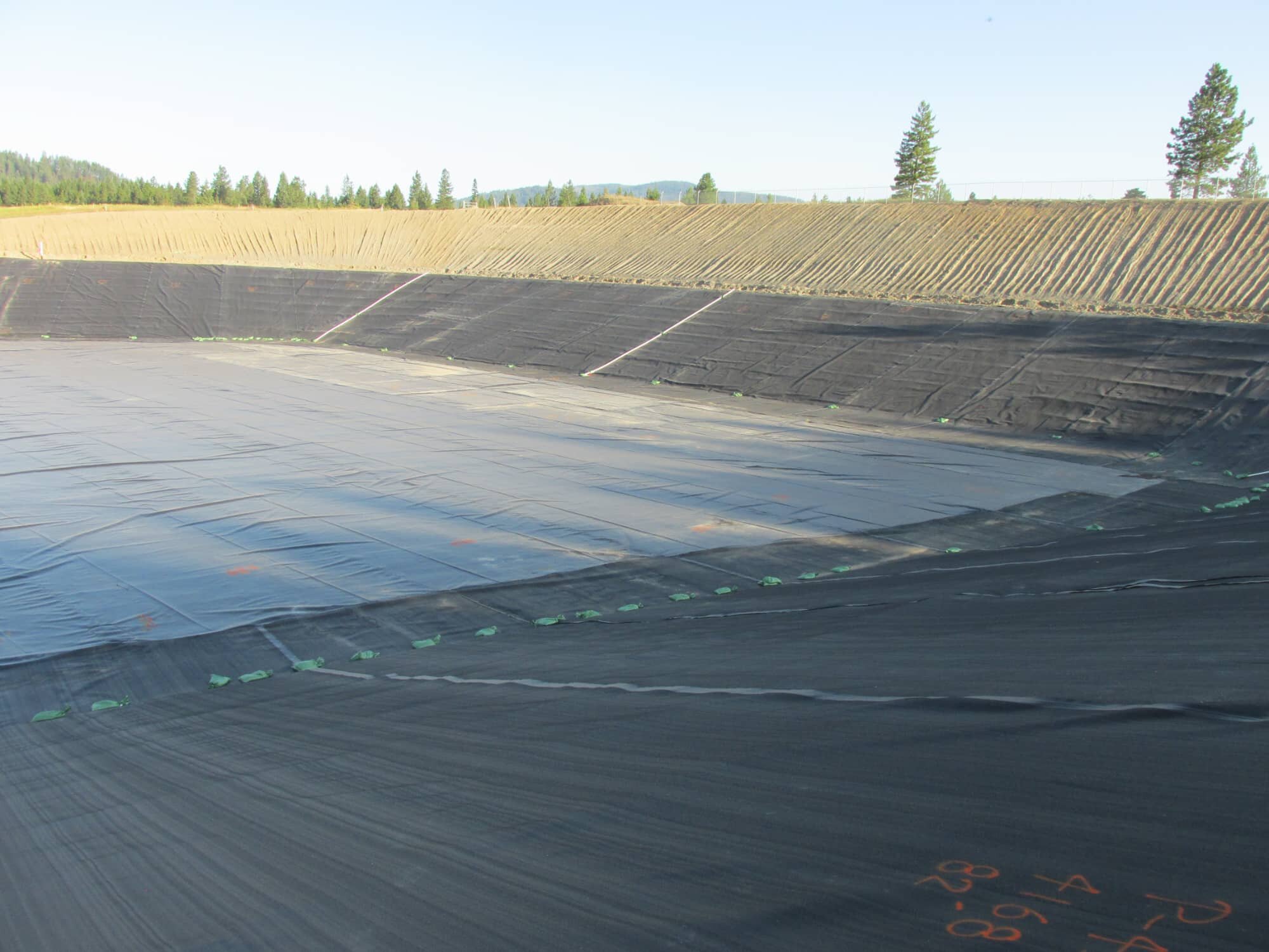
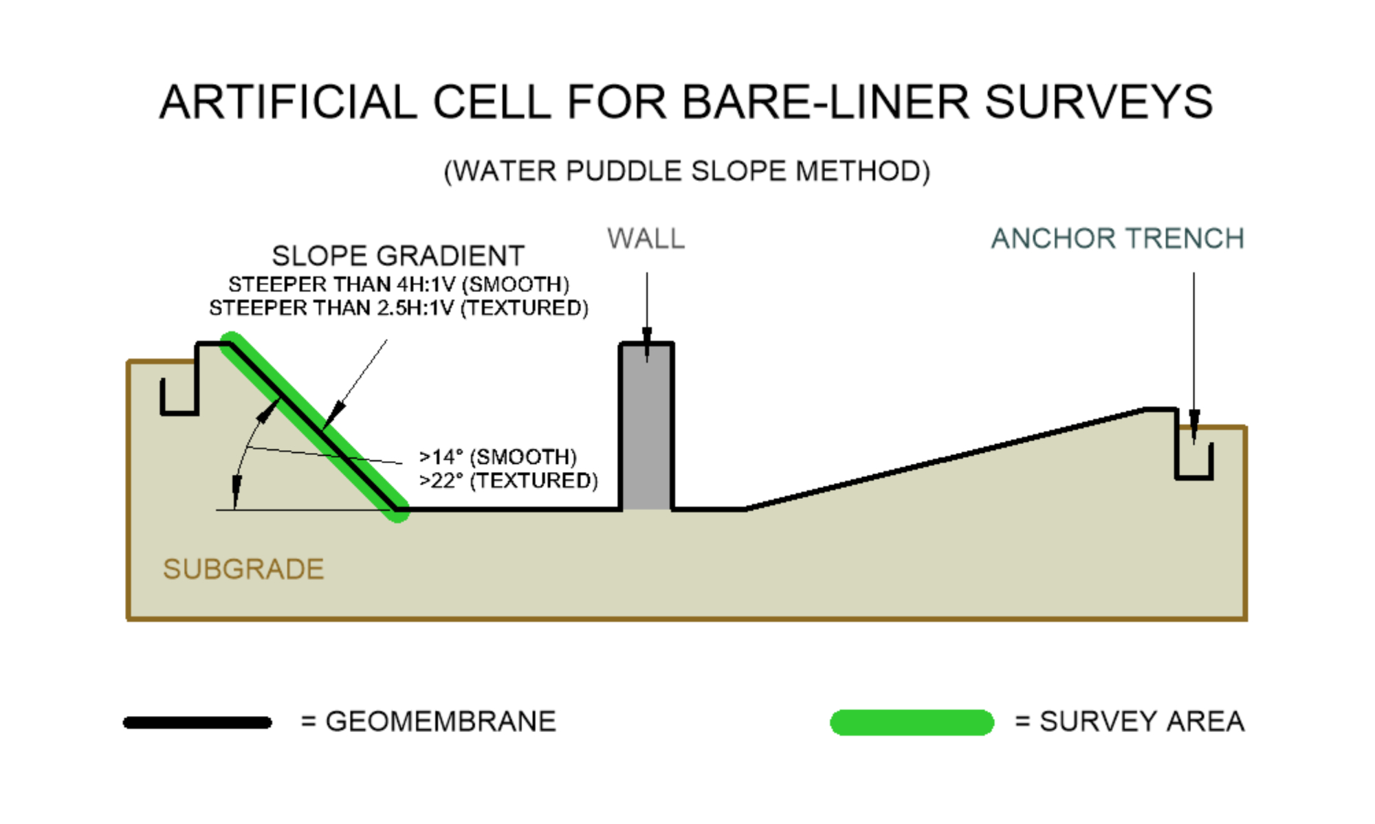
Smooth side slopes with a moderate to severe inclined plane angle greater than 14° (slope gradient steeper than 4H:1V), or textured side slopes with a moderate to severe inclined plane angle greater than 22° (slope gradient steeper than 2.5H:1V)
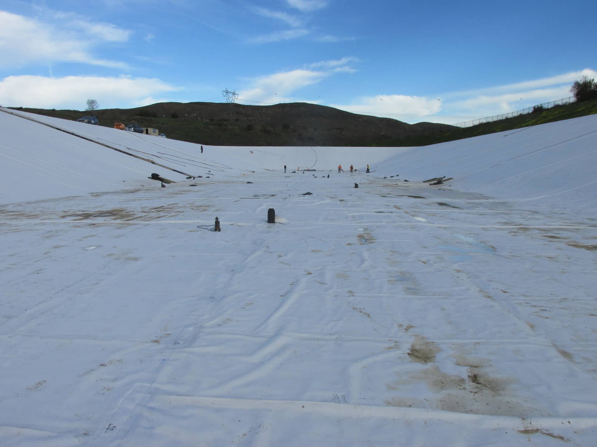
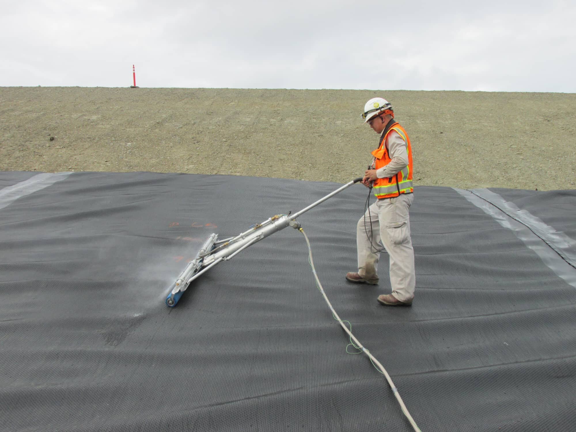
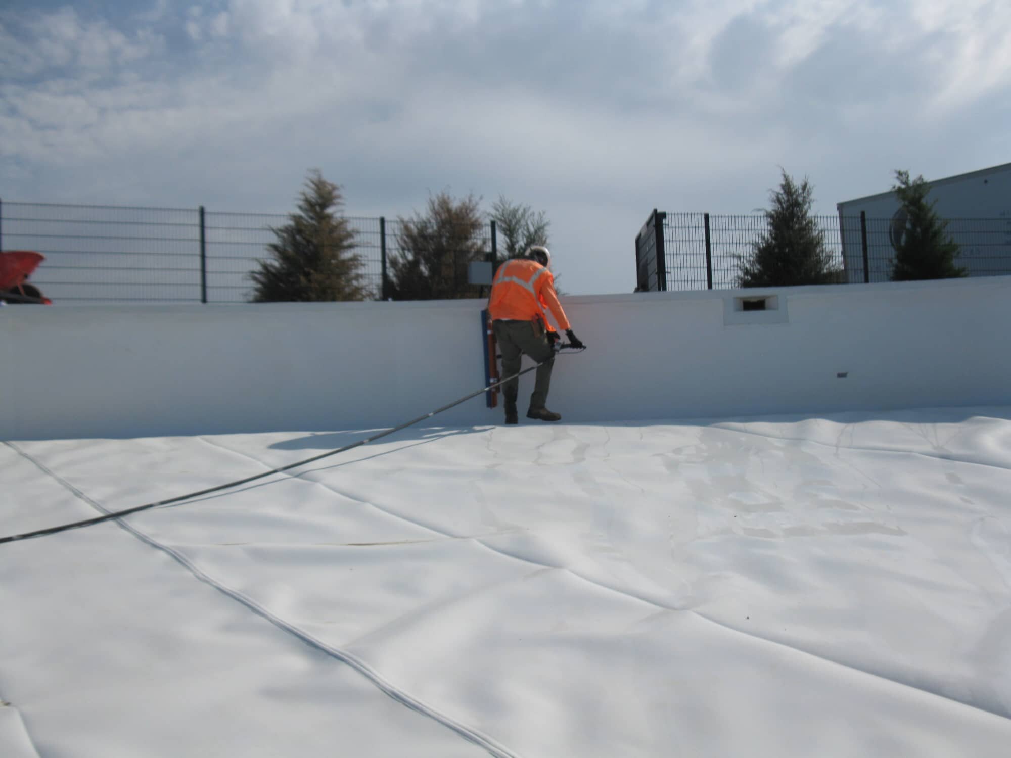
For slopes that are steep and cannot be walked on, this method puzzles it's way in to being the best fitment for this situation. The Water Puddle Slope Method is performed by pulling a probe up the face of the slope along the survey line starting from the toe of the slope. Once the probe reaches the crest, the probe is released down the same survey line until it reaches the bottom. The probe is transitioned to the next survey line and the process repeats. When a penetration, defect, or damage on the geomembrane is encountered, the water sprayed from the probe completes a circuit. This connection, or electrical continuity, is translated through a high frequency audible tone and notifies the technician.
(280 kPa)
approximately 100 ft (30 m)
side slopes
See our Preparations and Requirements Guide for General Contractors prior to an on-site leak detection service.

PREP Guide Single-Lined Systems

PREP Guide Double-Lined Systems
Click to view our Specifications Guide for the Electrical Leak Detection Quality Assurance Program using this method.

SPEC Guide Single-Lined Systems

SPEC Guide Double-Lined Systems
Click to view >

Click to view >
Service ID
D7002 - PUDW
Water Puddle Wall
COVERAGE
DESCRIPTION
REQUIREMENTS
DOWNLOADS
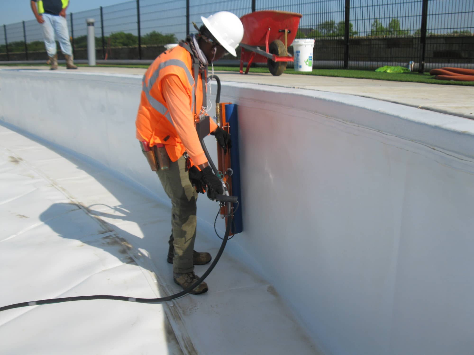
Vertical standing walls up to 8 ft (2.5 m)
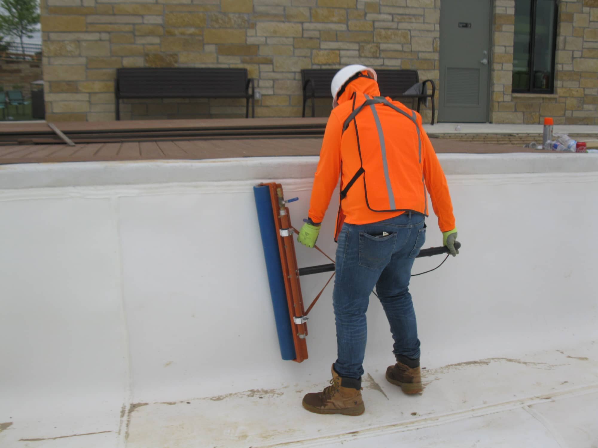
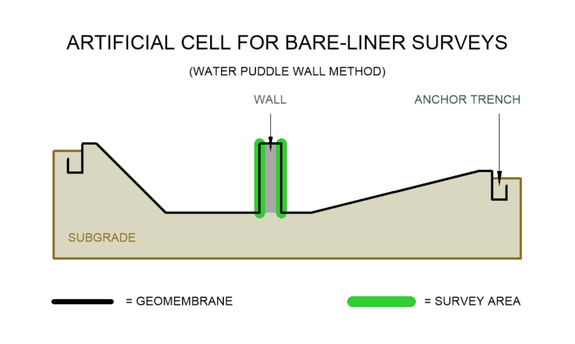
Having a geomembrane system installed along the walls of an embankment dam or a containment reservior should never be compromised. These geomembrane-lined walls serve two purposes: to prevent the contained liquid from seeping out of the cell and to provide an effective barrier to seepage. That's why checking the integrity of a geomembrane-lined wall using the Water Puddle Wall Method is highly important and should never be neglected. This method is performed by applying the probe against the vertical wall in a motion similar to "painting" a wall. The survey method can be performed by surveying the wall in a horizontal or vertical fashion. When a penetration, defect, or damage on the geomembrane is encountered, the water sprayed from the probe completes a circuit. This connection, or electrical continuity, is translated through a high frequency audible tone and notifies the technician.
(280 kPa)
approximately 100 ft (30 m)
See our Preparations and Requirements Guide for General Contractors prior to an on-site leak detection service.

PREP Guide Single-Lined Systems

PREP Guide Double-Lined Systems
Click to view our Specifications Guide for the Electrical Leak Detection Quality Assurance Program using this method.

SPEC Guide Single-Lined Systems

SPEC Guide Double-Lined Systems

Service ID
D7240 - SPKC
Spark Test
Survey method is currently unavailable.
COVERAGE
DESCRIPTION
REQUIREMENTS
DOWNLOADS
Sections of bare geomembrane in between welded seams or edges along the floor areas or side slopes with a slight inclined plane angle of 14° or less (slope gradient of 4H:1L or shallower)
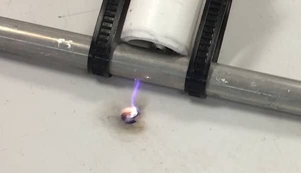
The method that paved way for new types of surveys and that "sparked" the initial standards of the leak detection industry is the worldly-known Spark Test Method. This method is performed by pushing a probe along the floor area, or in parallel with the face of the slope. The Spark Test Method (also known as the Electrical Capacitance Technique) consists of a high voltage pulsed power supply that charges a capacitor formed by three required materials: the underlying conductive layer, the non-conductive isolation layer, and a coupling pad. Only areas where a leak is present will a capacitive discharge occur. A portable detector unit converts the discharge into an audible tone and alarms the technician.
geomembrane
Currently not available
Click to view >


Click to view >

BEST IN BARE-LINER SURVEYS
"Most Accurate Survey Method"
Service ID
D7953 - ARCC
Arc Test
Survey method is currently unavailable.
COVERAGE
PROCESS
REQUIREMENTS
DOWNLOADS
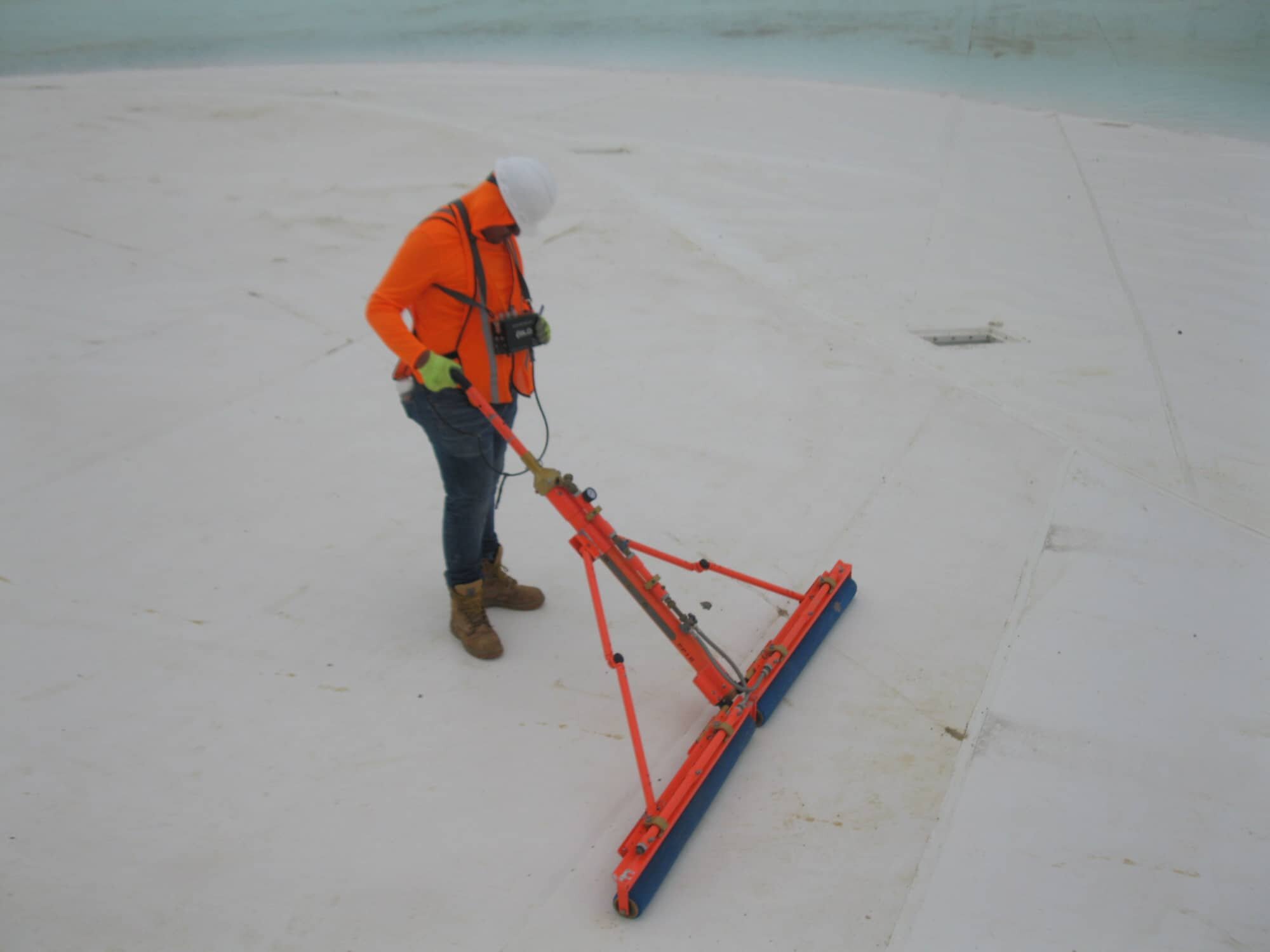
Floor areas or side slopes with a slight inclined plane angle less than 14° (slope gradient of 4H:1L or shallower)
The Arc Test Method is practical when a water source is unavailable, or when liquid is not allowed to enter the cell. The power source ranges between 6,000 to 30,000 Volts and is swept across the floor, side slopes, or vertical walls of a conductive-backed geomembrane. The test probe locates the areas of where current completes the circuit through a leak or penetration in the liner. When the probe contacts a leak, a visible electrical arc is formed. The current flow is converted into an audible tone and alarms the technician that a leak has been detected.
welding machine
Currently not available
* Recognitions are based on gathered information and data collected since 2010 when compared to other survey methods provided by BLD.

