


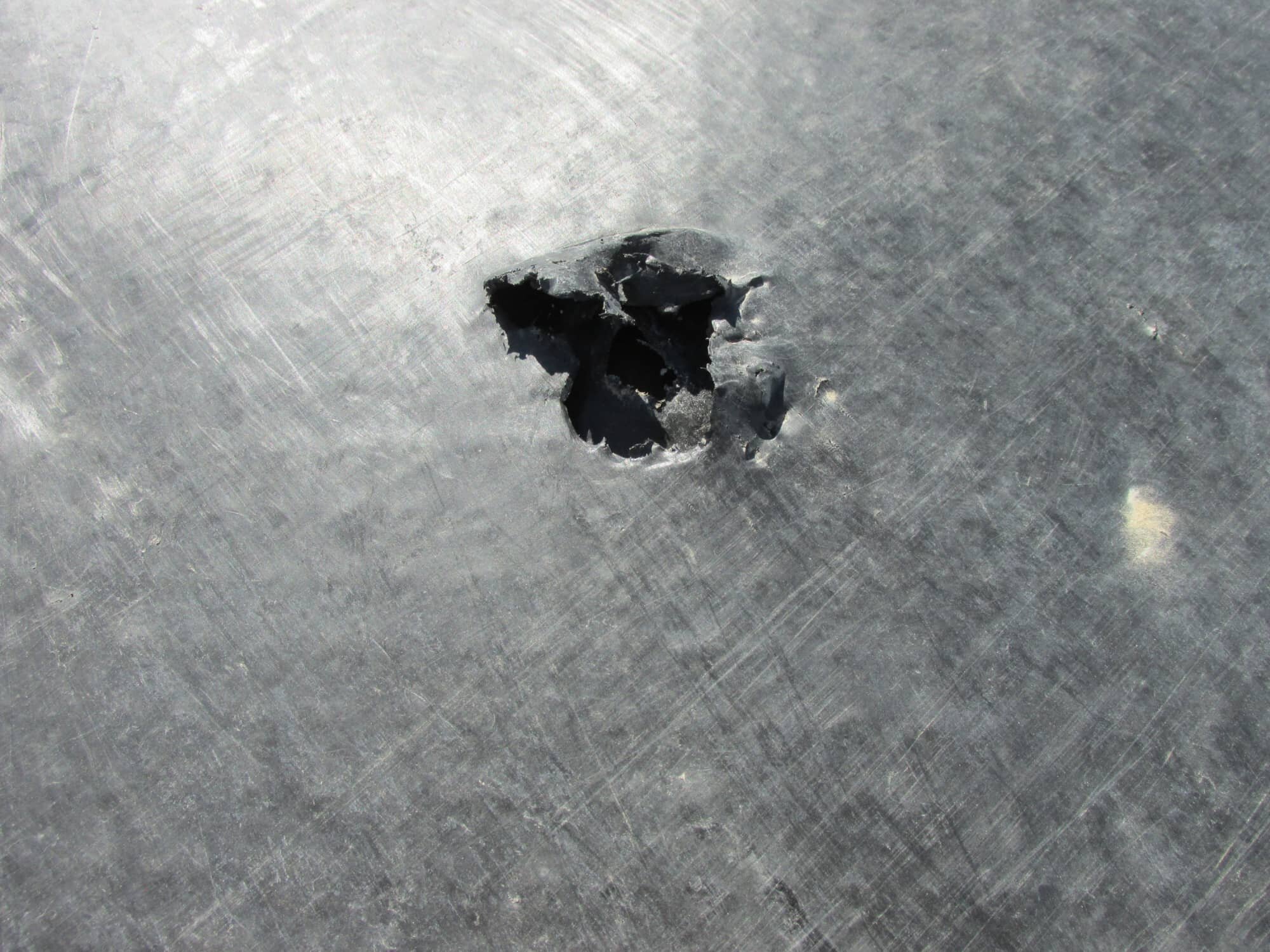
The leak detection method for water surveys is the most sensitive and accurate in locating leaks. The survey methods are commonly performed in applications where containment is required. When a water-covered penetration, defect, or damage in the geomembrane is encountered during a survey of the application, the anomaly completes a circuit. This connection, or electrical continuity, is translated through the survey probe and leak detection device. The electronic device converts the current signal into a high frequency audible tone and alarms the technician. This is the most preferred type of survey for all types of liquid containment and surface impoundment applications.
NOTE: Water Surveys do not necessarily require "water" to be in the application. While performing water surveys using a variety of leak detection methods, different mixtures of liquids and/or conductive elements (also referred to as liquid solution) may be present in the containment pond or application. The term "Water" or "Liquid Solution" are used to categorize general types of liquid relative to the leak detection process.
APPLICABLE ASTM STANDARDS
- ASTM D6747-15 - Selection of Techniques for Electrical Leak Location of Leaks in Geomembranes
- ASTM D7007-16 - Electrical Methods for Locating Leaks in Geomembranes Covered with Water or Earthen Materials

Click to view >

Featured Project

BEST IN WATER SURVEYS
"Most Accurate Survey Method For
Floor Areas"
"Most Leaks Located Per Area"
Service ID
D7007 - WADE
Shallow Water Wade
COVERAGE
DESCRIPTION
REQUIREMENTS
DOWNLOADS
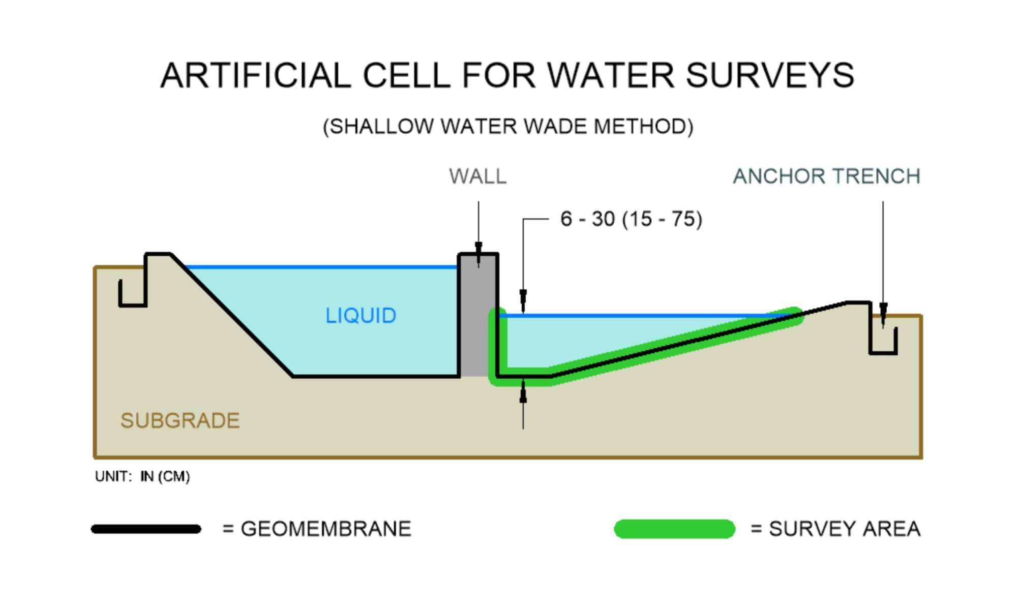
Floor areas, side slopes or vertical walls that contain a liquid solution depth between 6 to 30 in (15 to 75 cm)
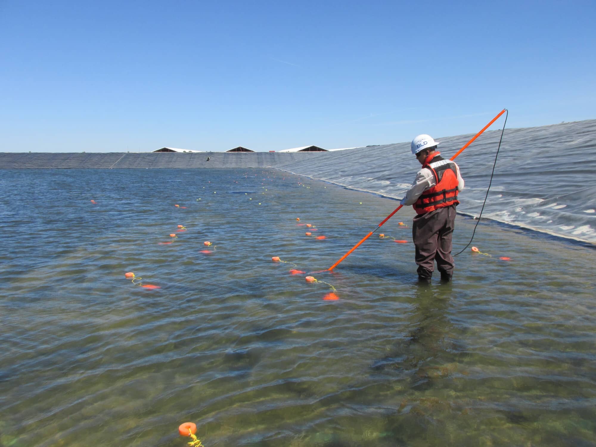
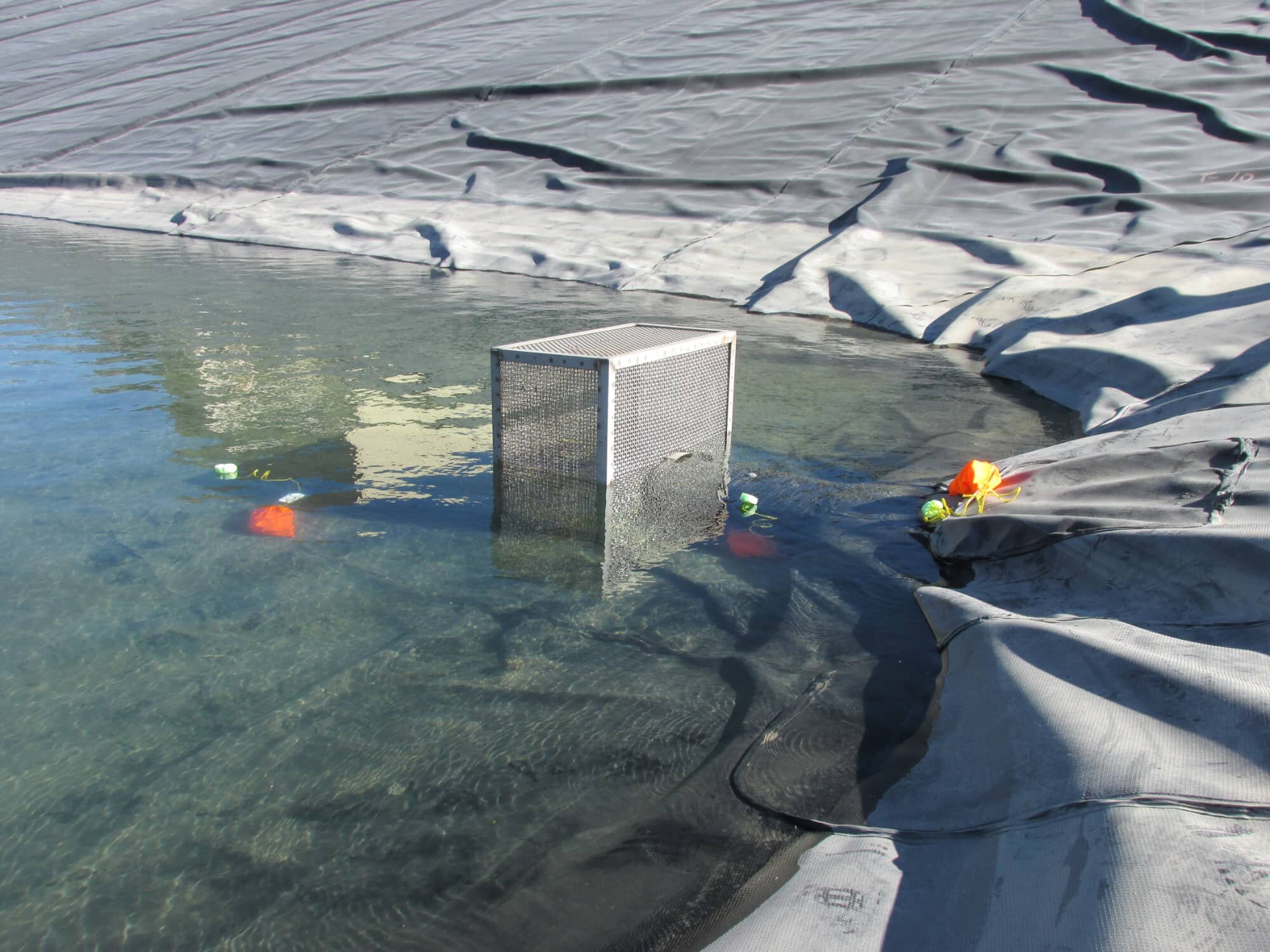
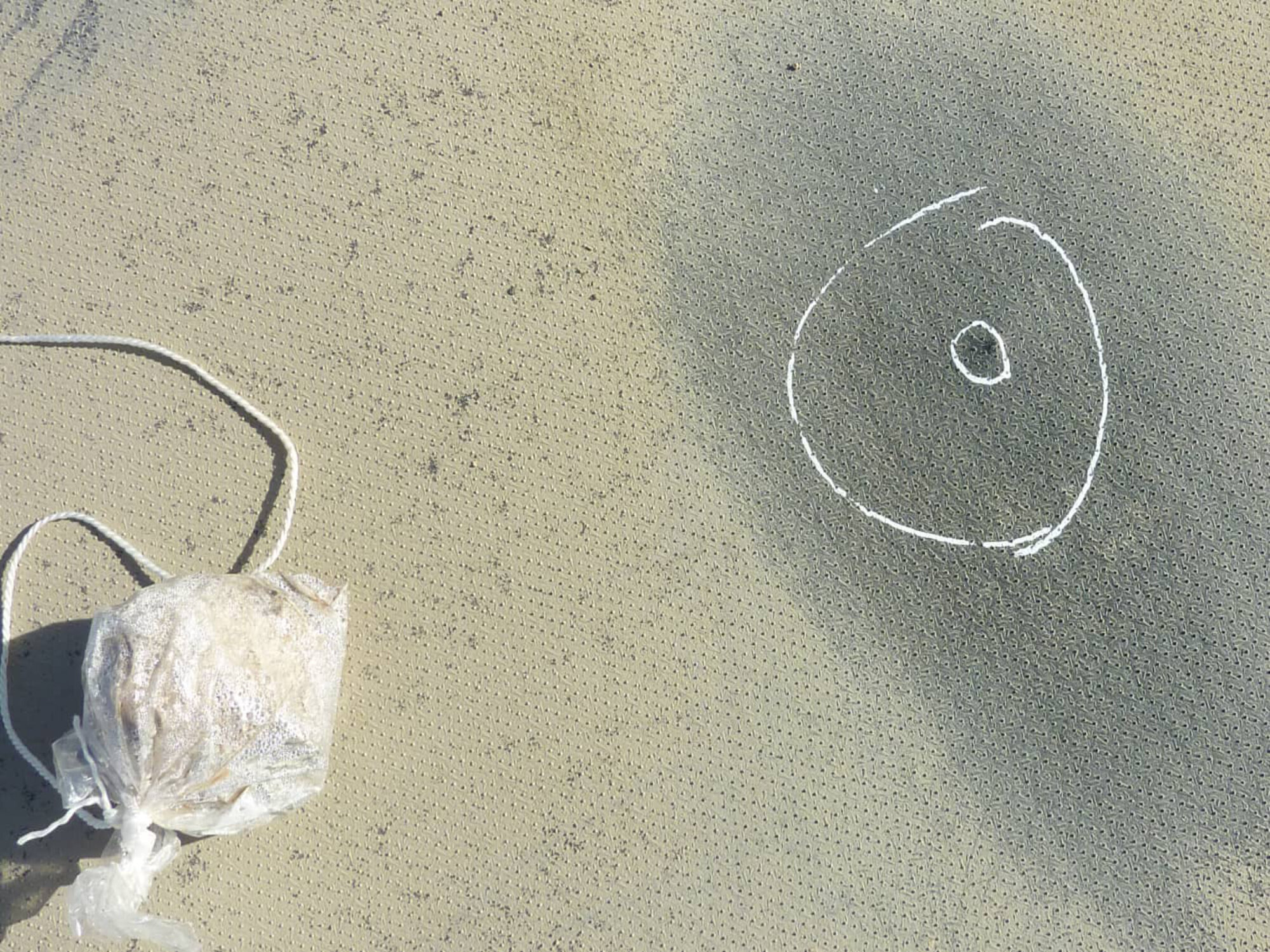
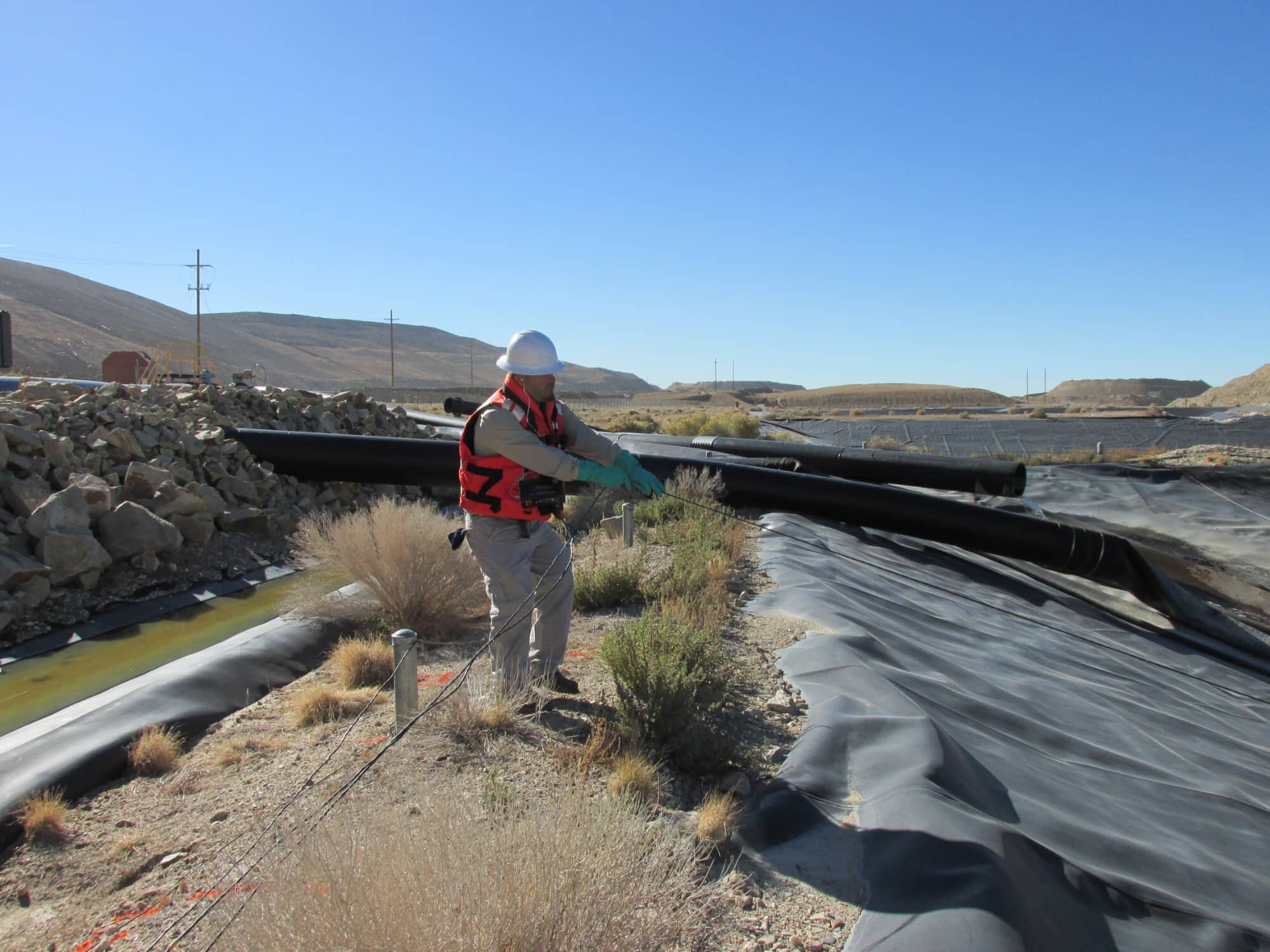
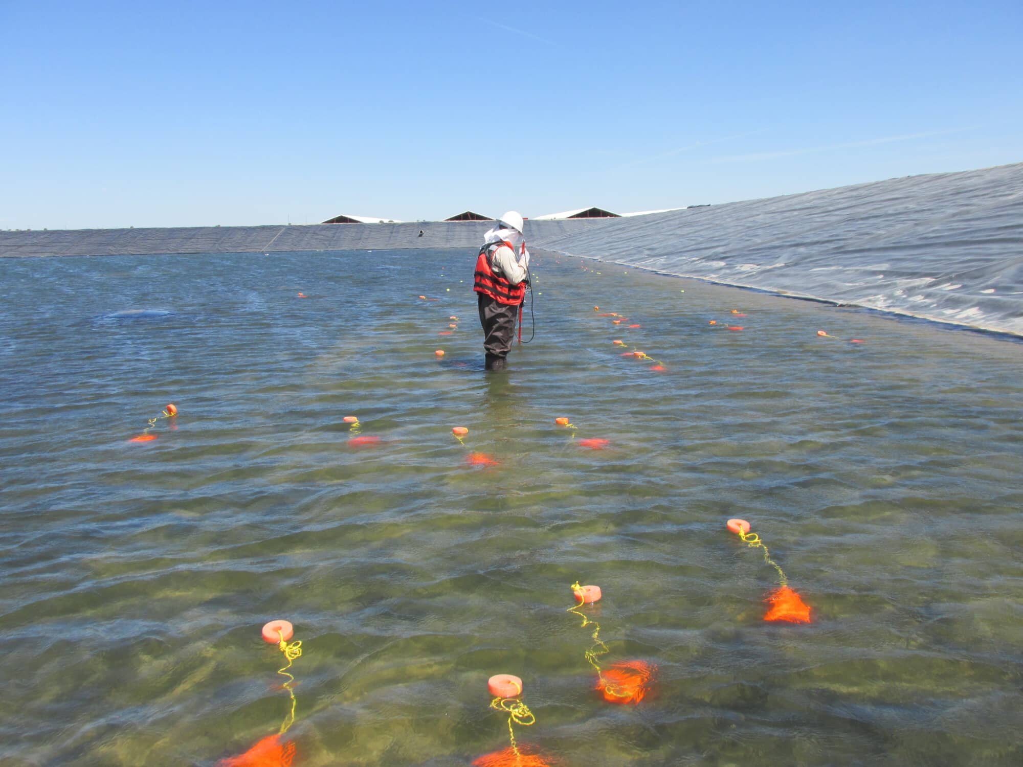
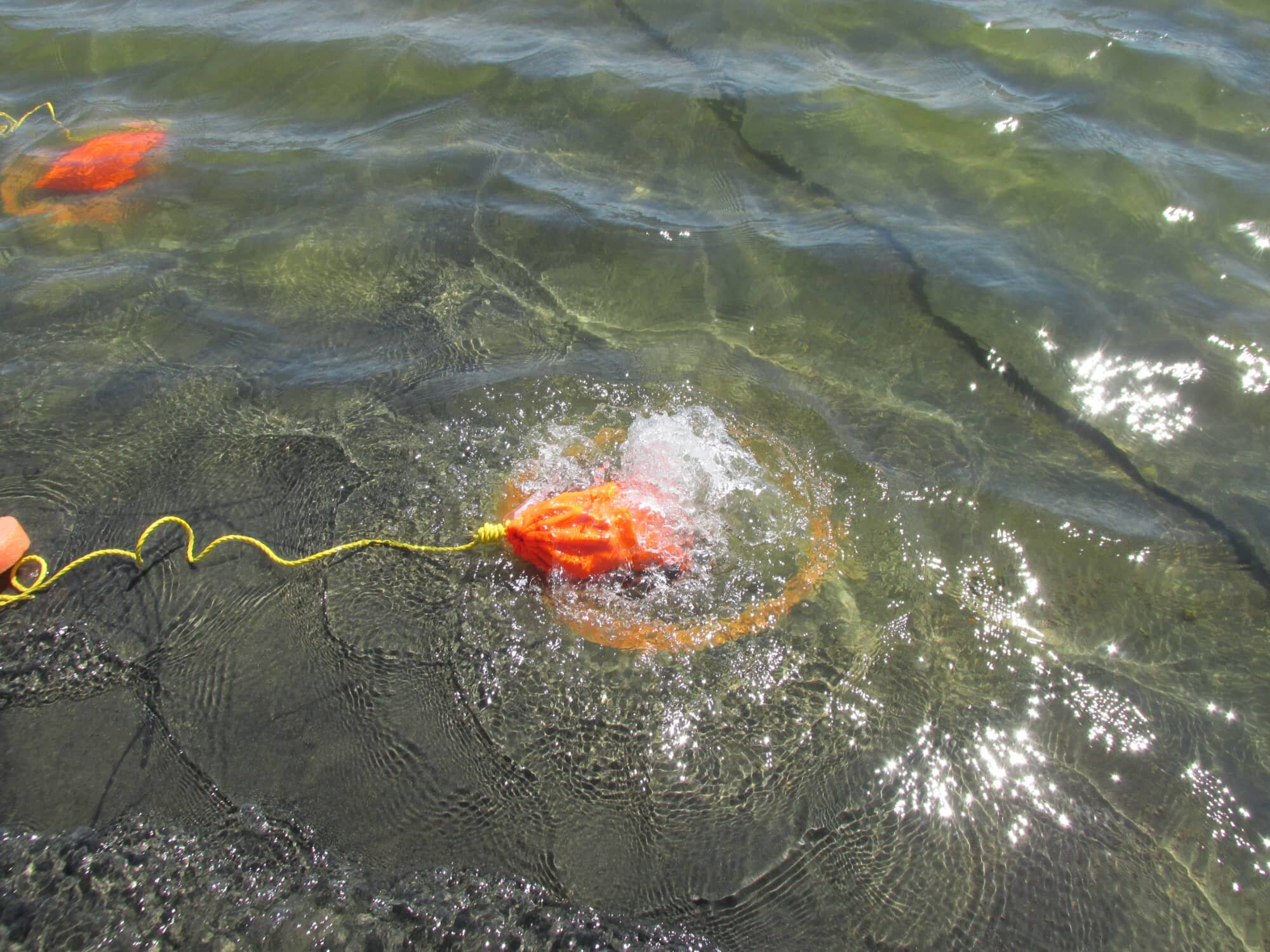
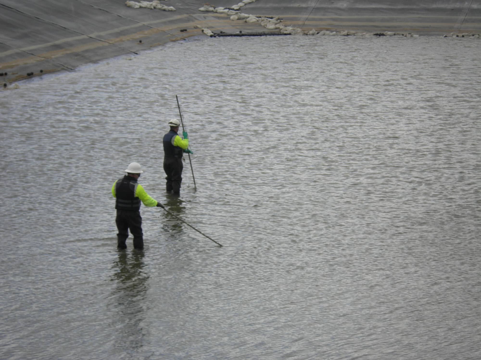
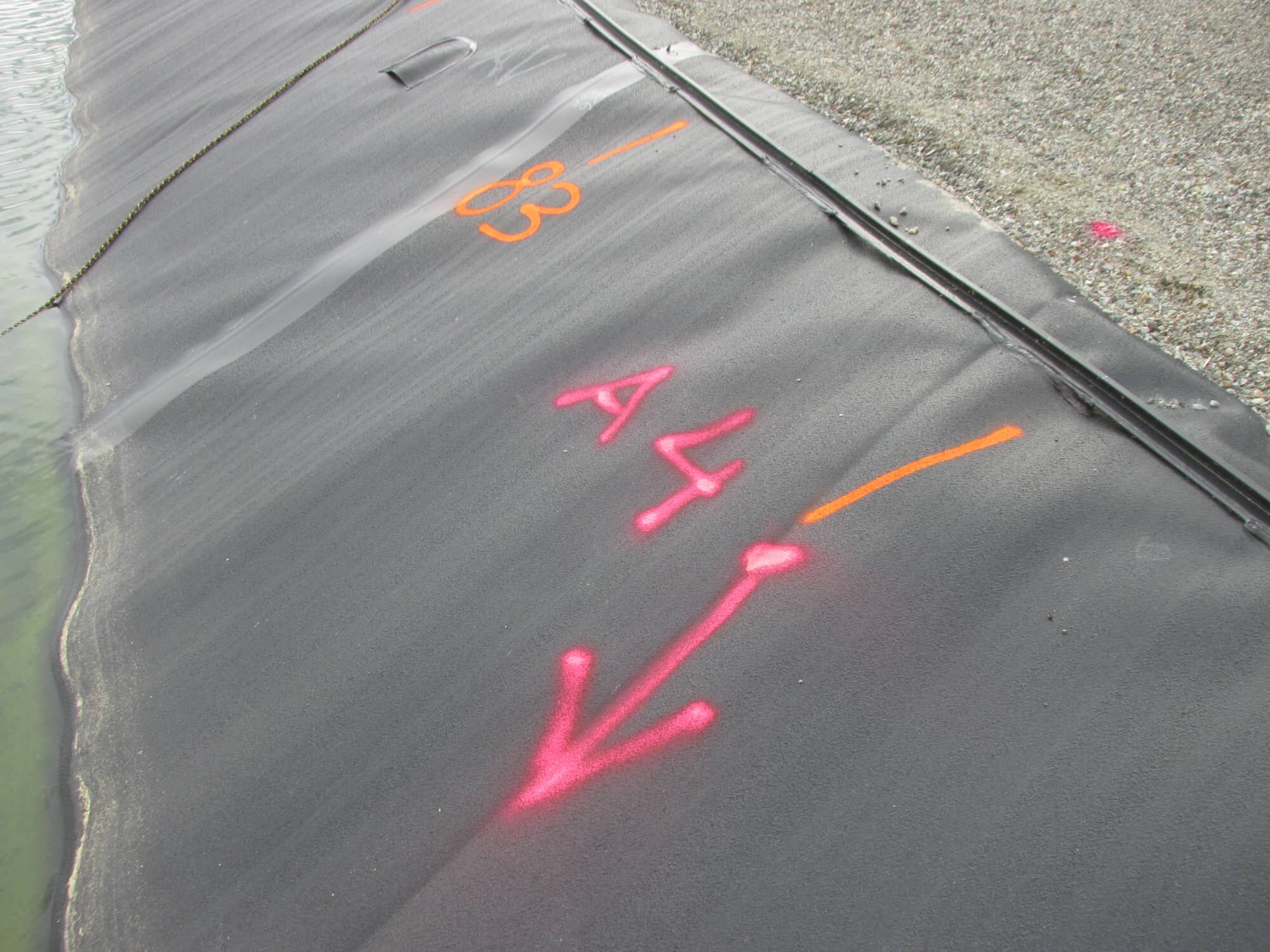
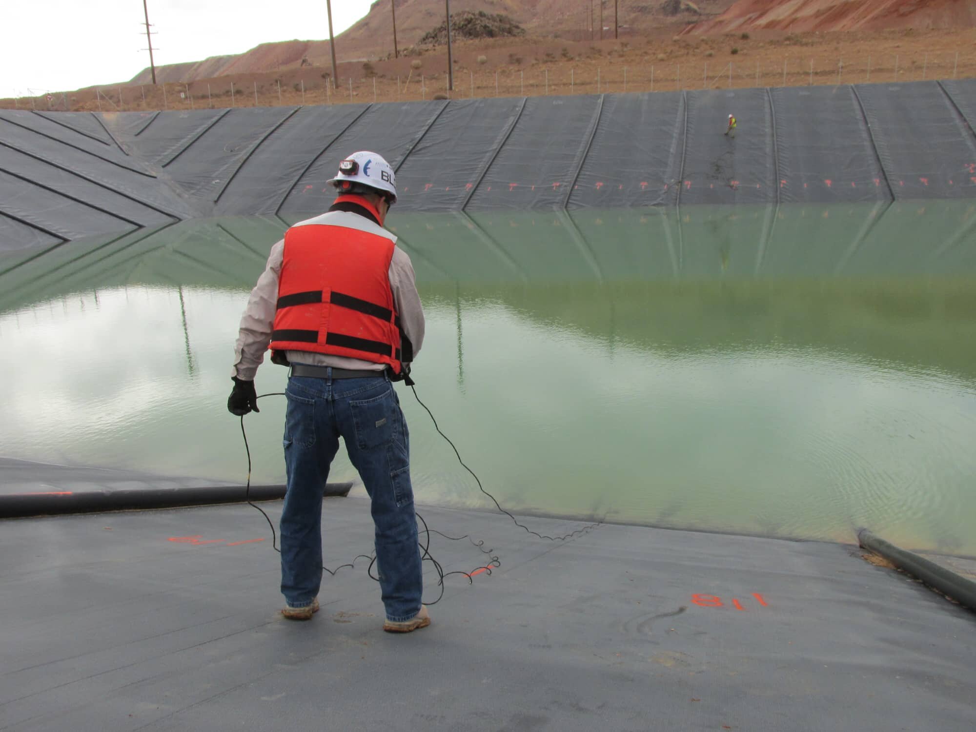
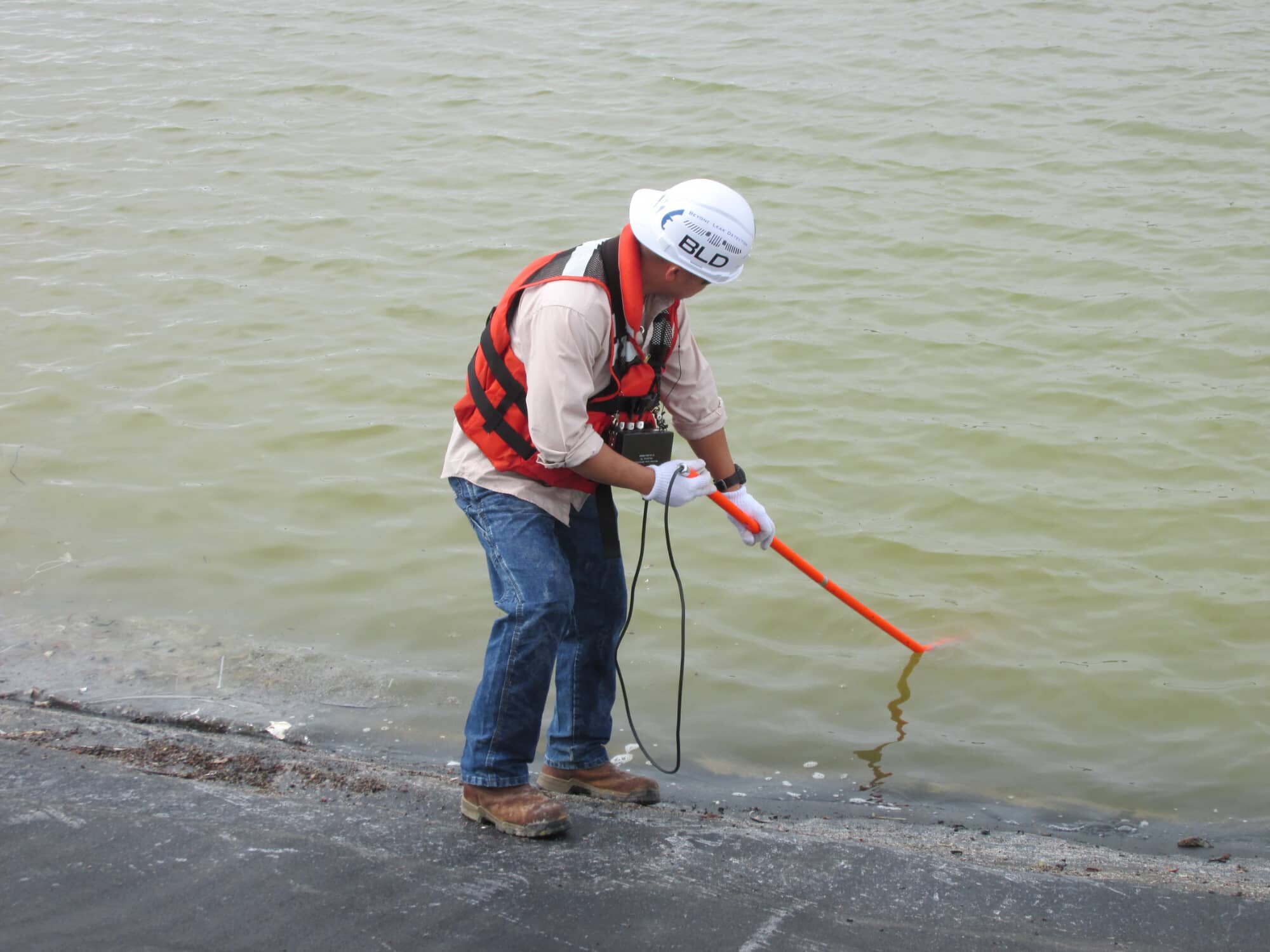
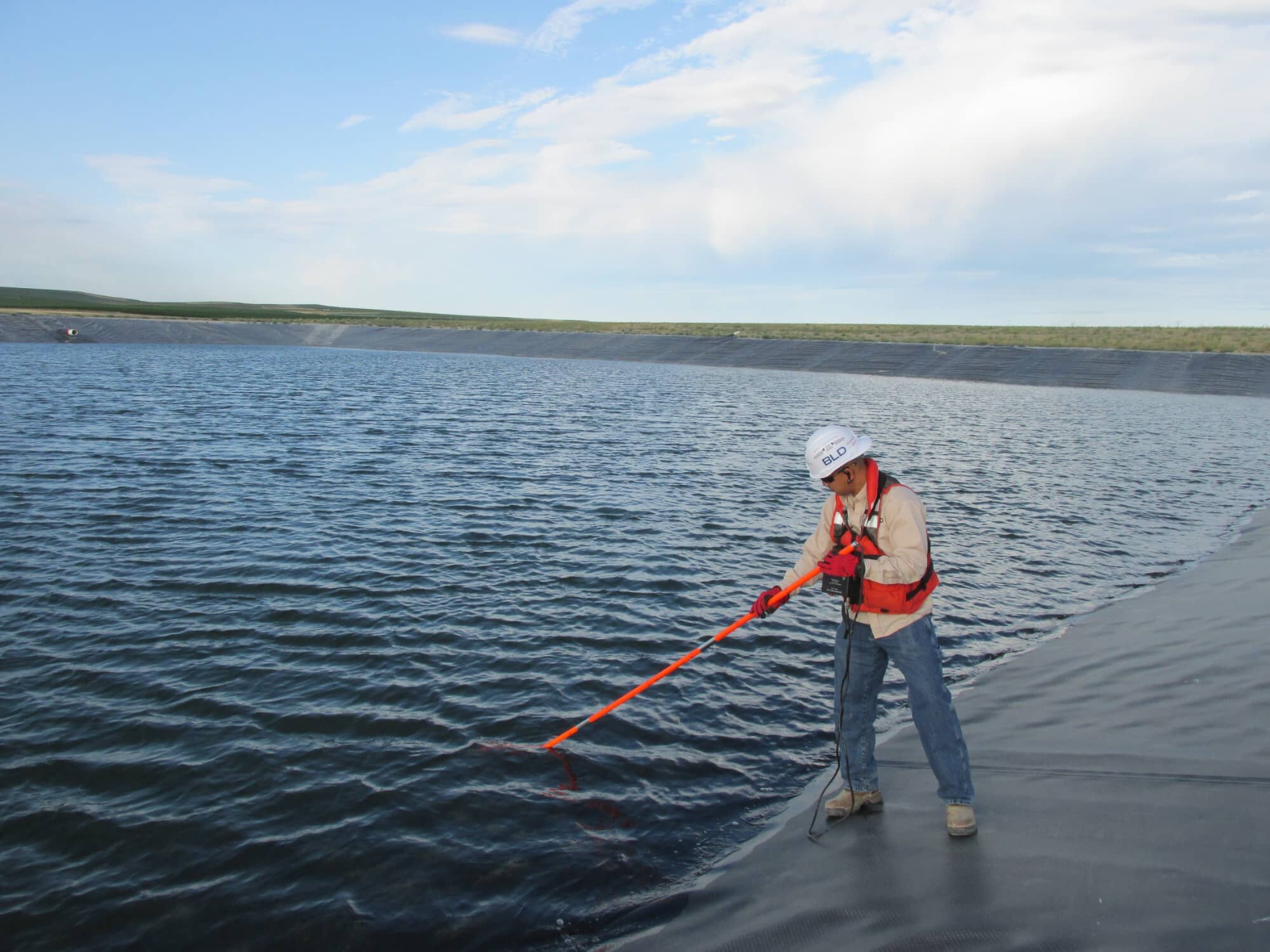
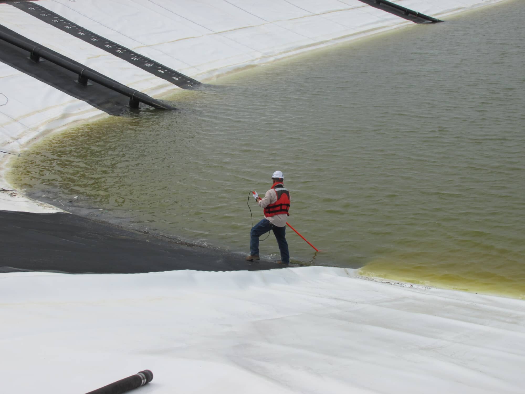
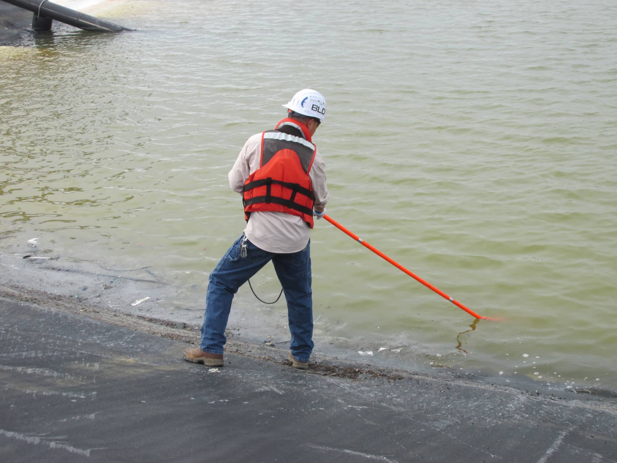
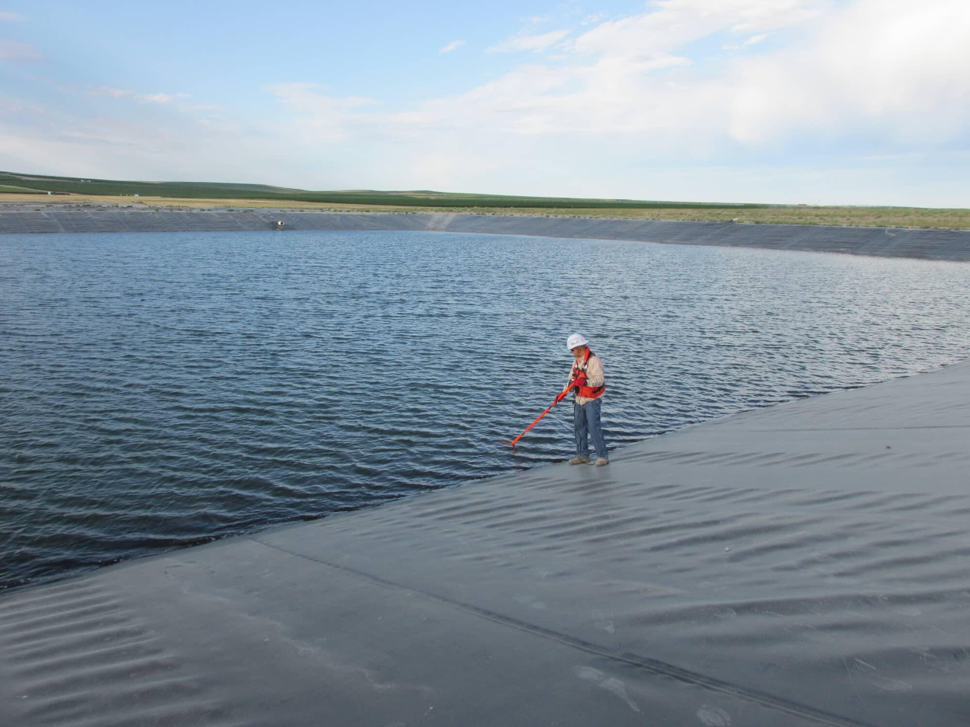
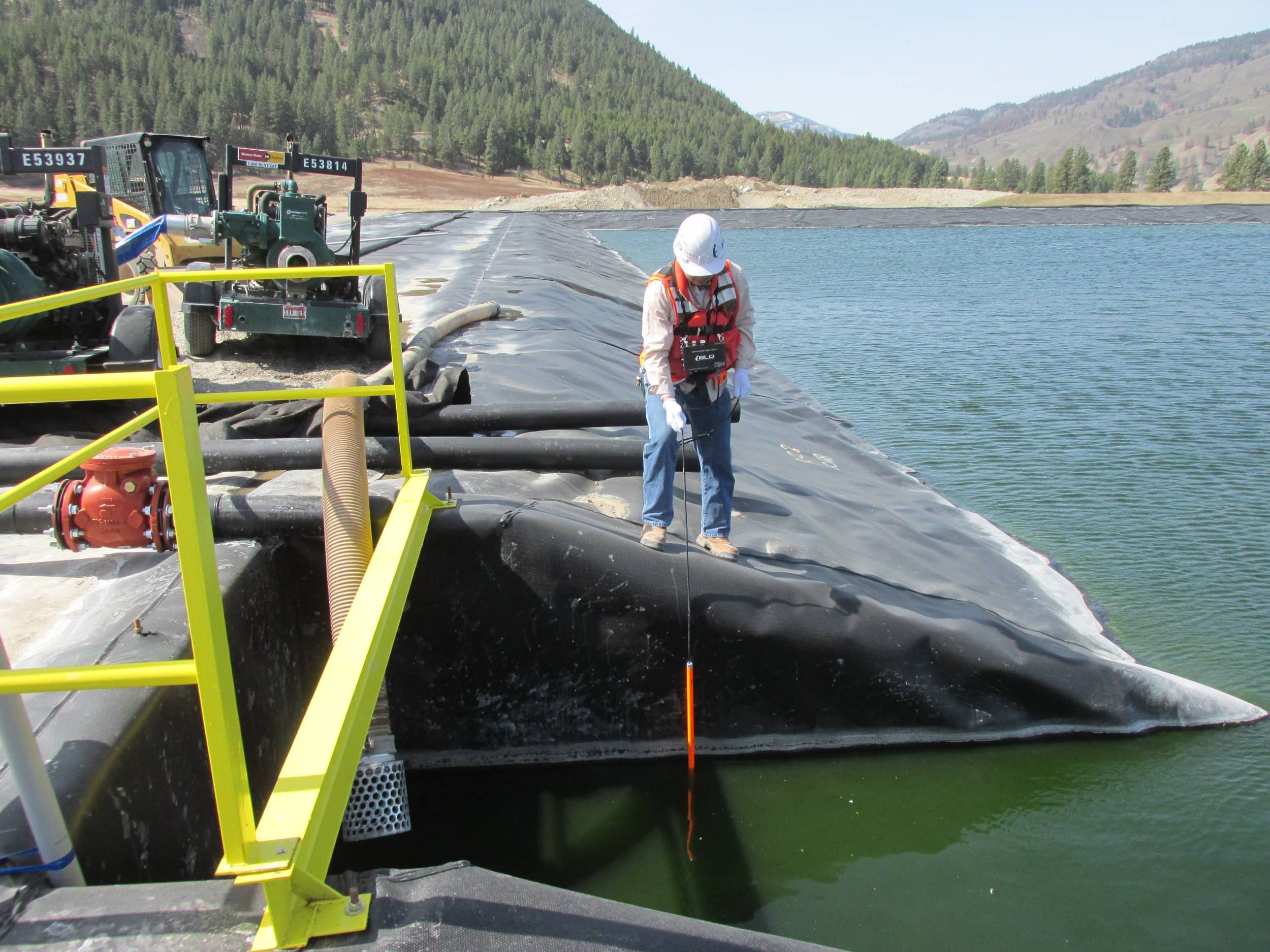
Undeniably the most recommended method among all water surveys, this method is performed by wading in the liquid solution with a water probe. During the survey, all defects and penetrations in all water-covered areas such as panels, patches, welds, beads, and seams will be tested. In addition, anomalies are pinpointed immediately during the survey and marked by using high-visibility weighted baggies with floats attached by a string. These anomalies are also referenced to a secondary mark with marking paint or markers on the bare-liner along the side slopes. This method ranks the highest among all water surveys by leading the pack with accuracy.
depth during entire survey
(spherical formation of trapped air pockets within liquid)
disturbed or moved until the repair process is complete
See our Preparations and Requirements Guide for General Contractors prior to an on-site leak detection service.

PREP Guide Single-Lined Systems

PREP Guide Double-Lined Systems
Click to view our Specifications Guide for the Electrical Leak Detection Quality Assurance Program using this method.

SPEC Guide Single-Lined Systems

SPEC Guide Double-Lined Systems

Service ID
D7007 - STOW
Shallow Water Tow
COVERAGE
DESCRIPTION
REQUIREMENTS
DOWNLOADS
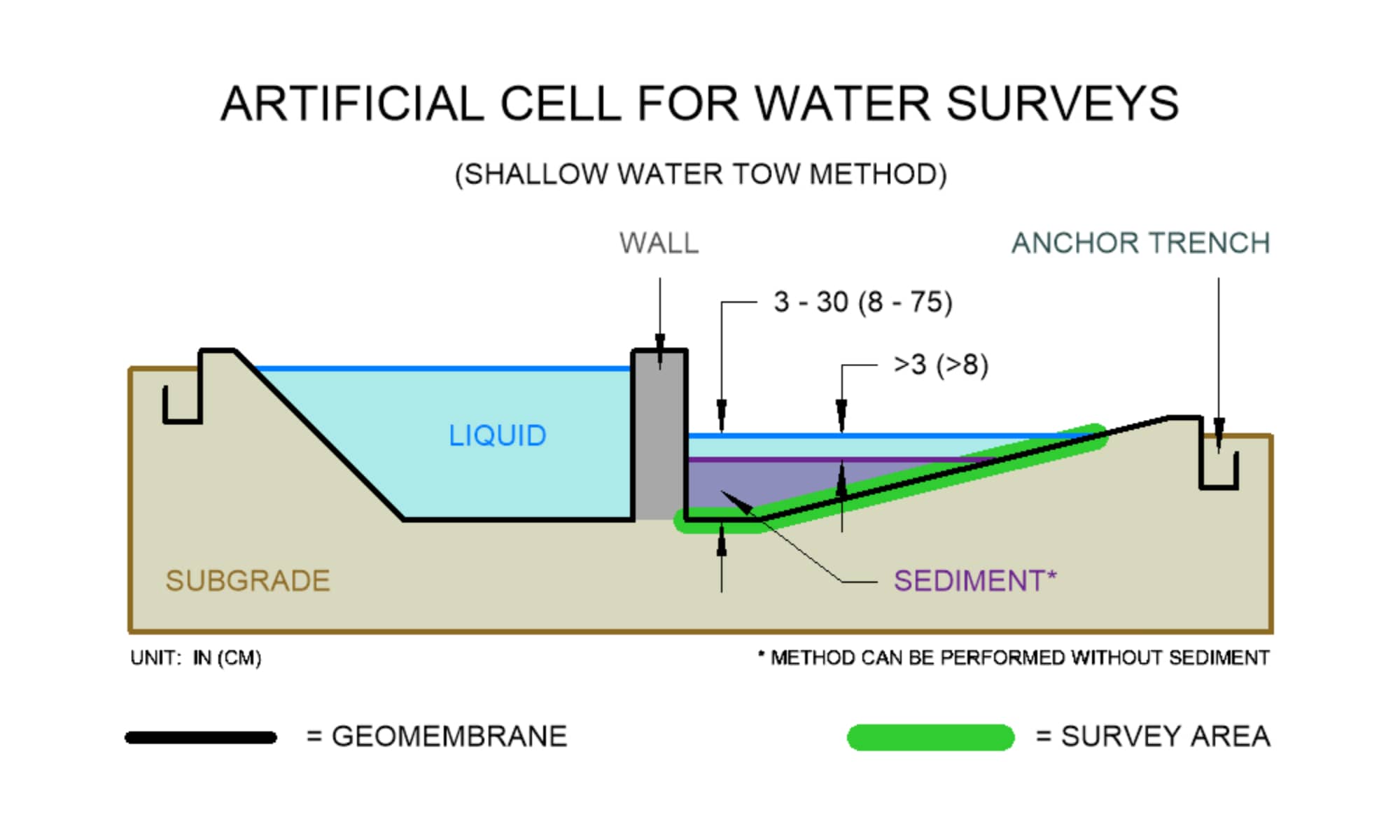
Floor areas and side slopes that contain a liquid depth between 3 to 30 in (8 to 75 cm)
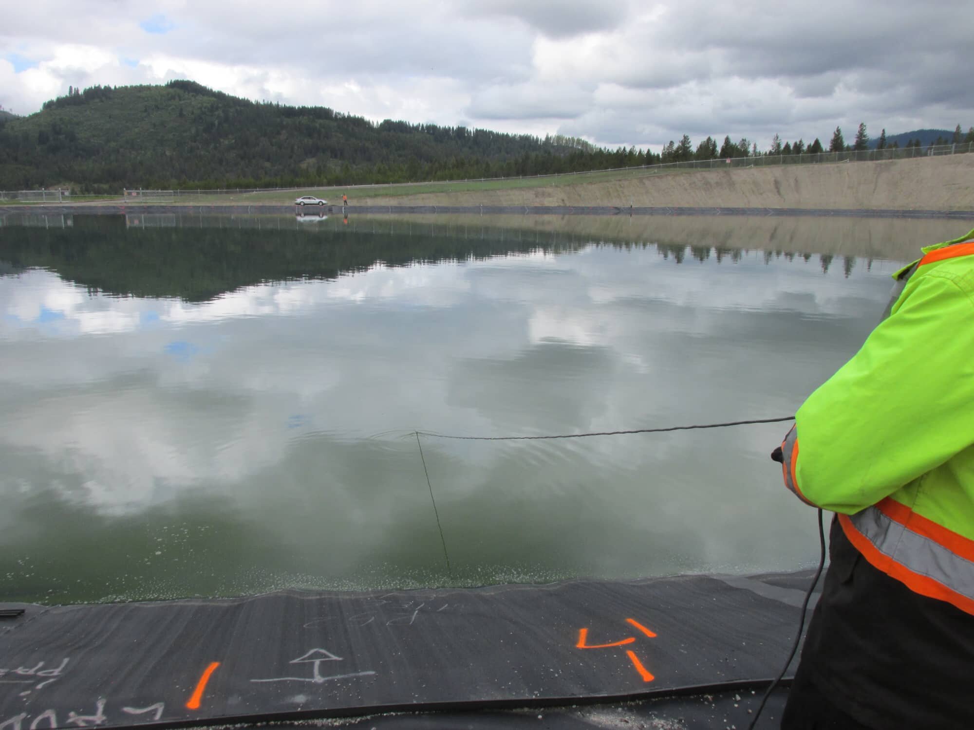
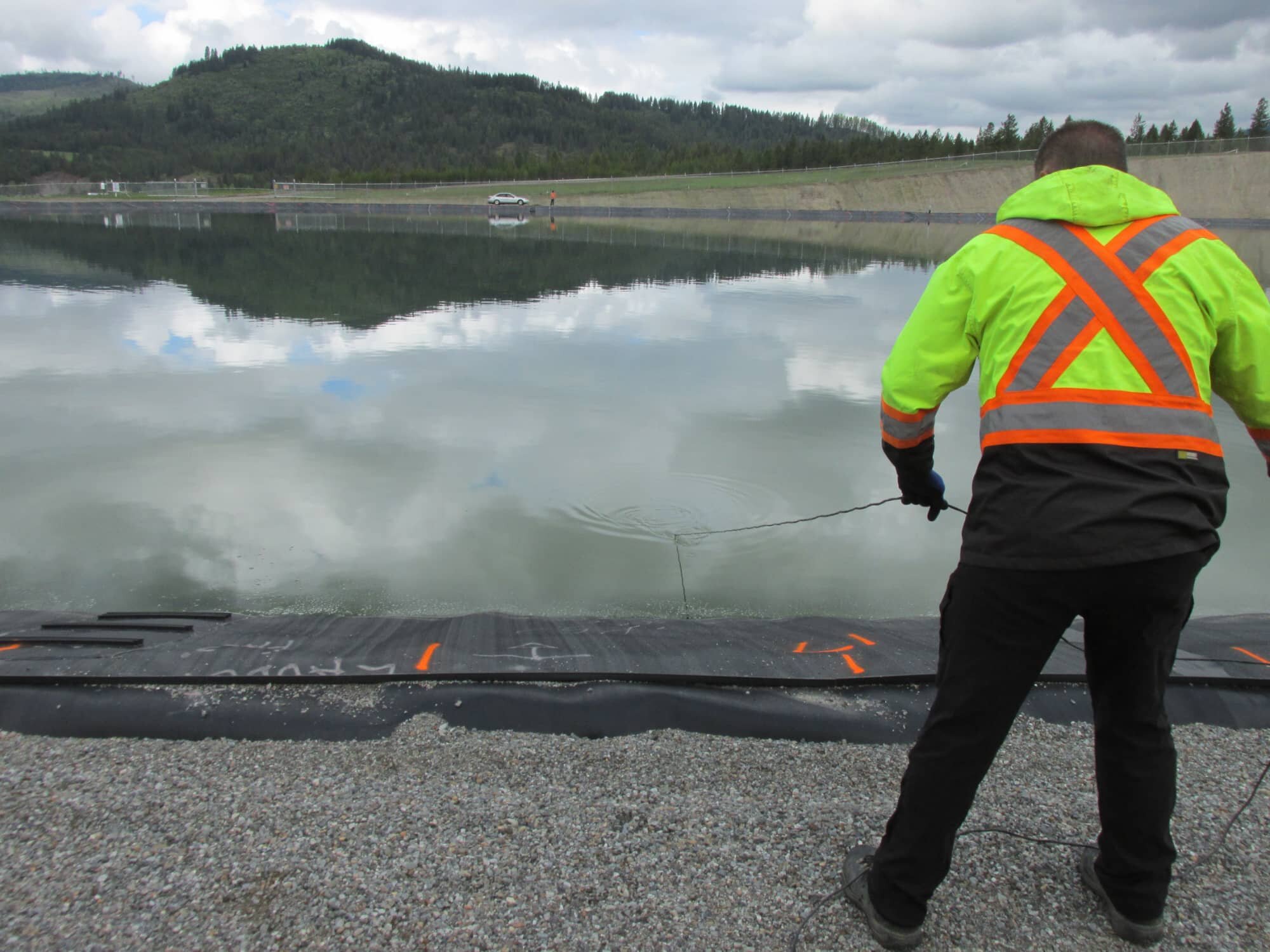
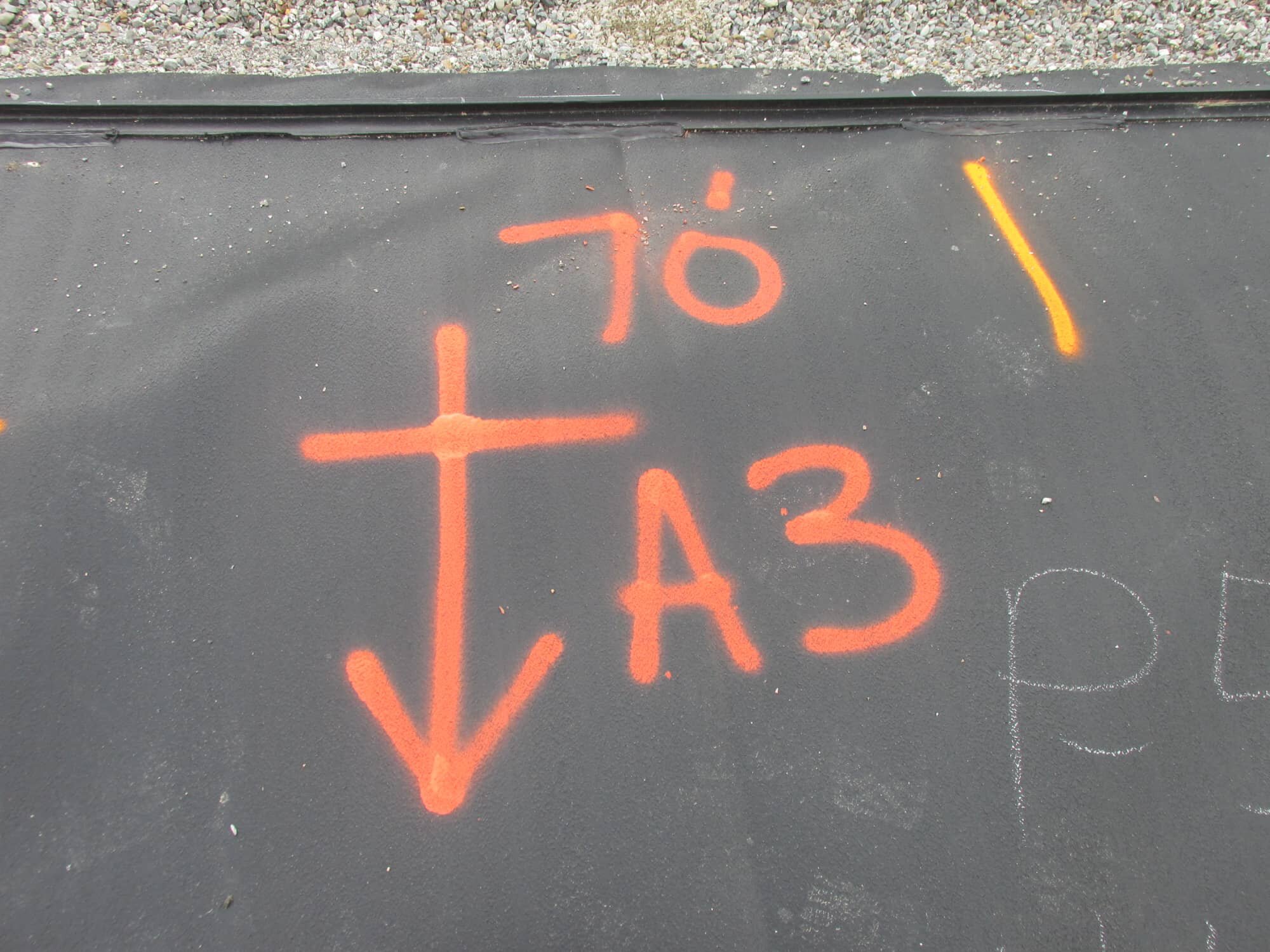
When an application contains elements to prevent technicians from wading in it such as hazardous liquid, chemicals, foul substances, thick sediment or sludge, the Shallow Water Tow Method is the perfect ingredient for being safe while performing a reliable water survey. During the survey, a technician and an assistant would stand on opposite banks of the application and drag a probe across the floor area and side slopes. The distance to the leaks are measured according to the measurement labeling system on the probe cord. They are documented on the side slopes with a location and reference mark. This method is perfect for sludge and sediment applications.
depth is too shallow to maintain a minimum depth level of
3 in (8 cm)
covered until the pinpoint and repair process is complete
See our Preparations and Requirements Guide for General Contractors prior to an on-site leak detection service.

PREP Guide Single-Lined Systems

PREP Guide Double-Lined Systems
Click to view our Specifications Guide for the Electrical Leak Detection Quality Assurance Program using this method.

SPEC Guide Single-Lined Systems

SPEC Guide Double-Lined Systems
Click to view >

Click to view >

Featured Project

BEST IN WATER SURVEYS
"Ranks Highest in Leak Detection
Sensitivity"
"Most Popular Survey Method For
Containment Systems"
Service ID
D7007 - DTOW
Deep Water Tow
COVERAGE
DESCRIPTION
REQUIREMENTS
DOWNLOADS
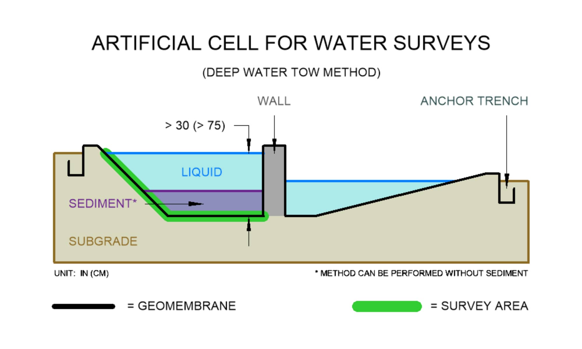
Floor areas and side slopes with a minimum liquid depth of 30 in (75 cm)
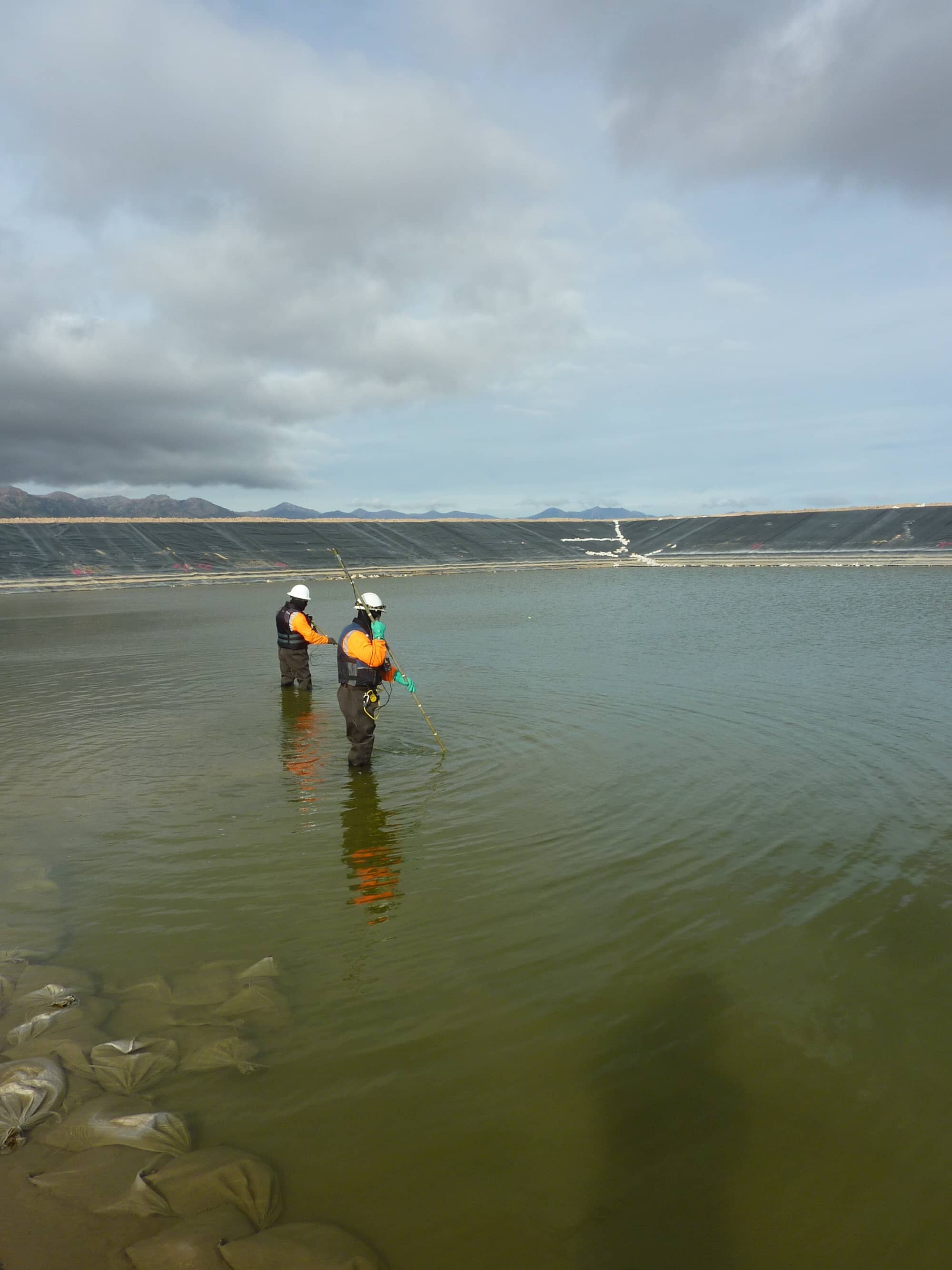
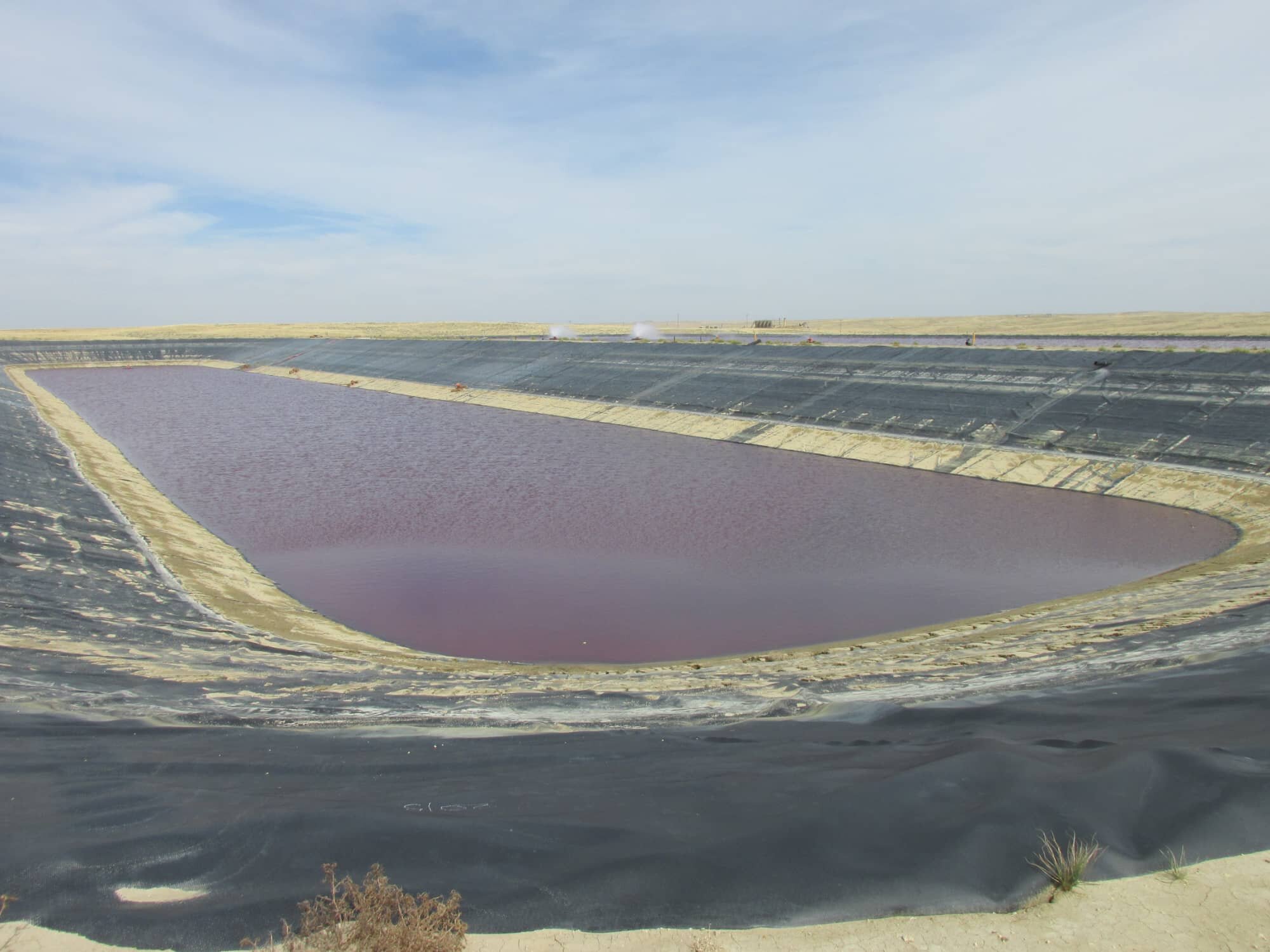
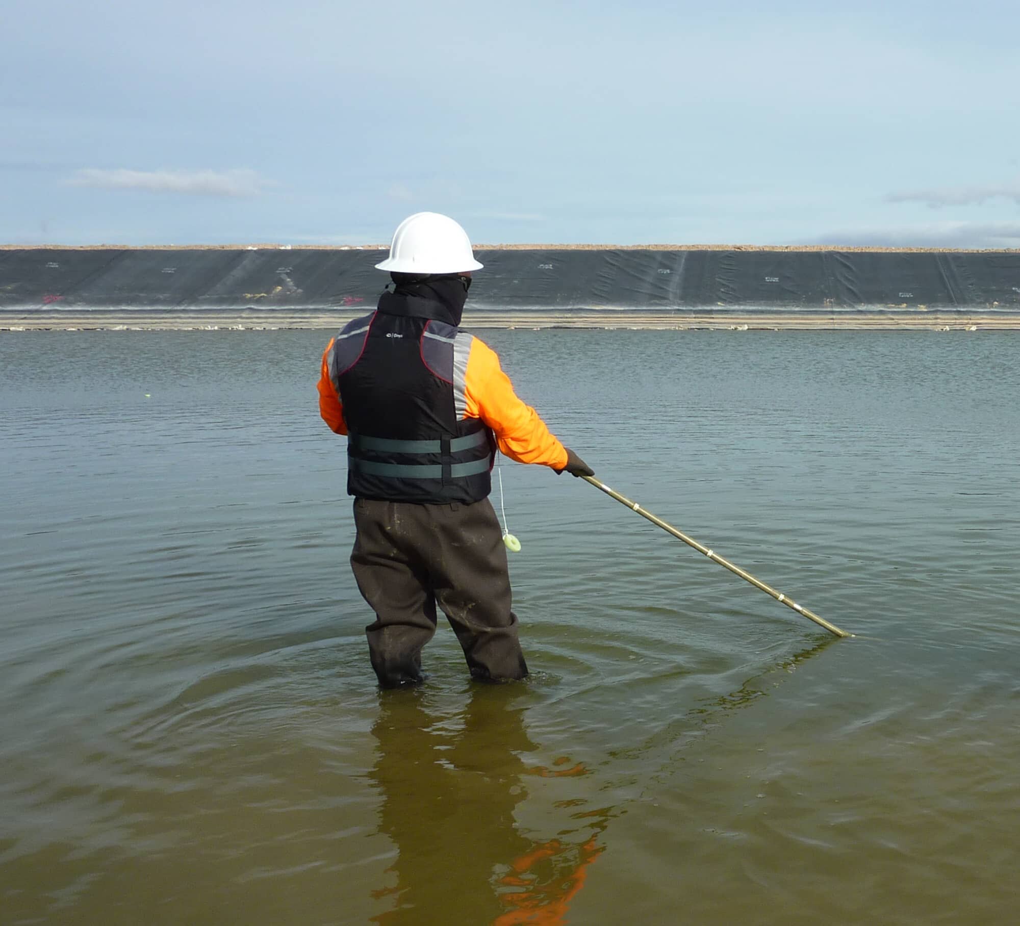
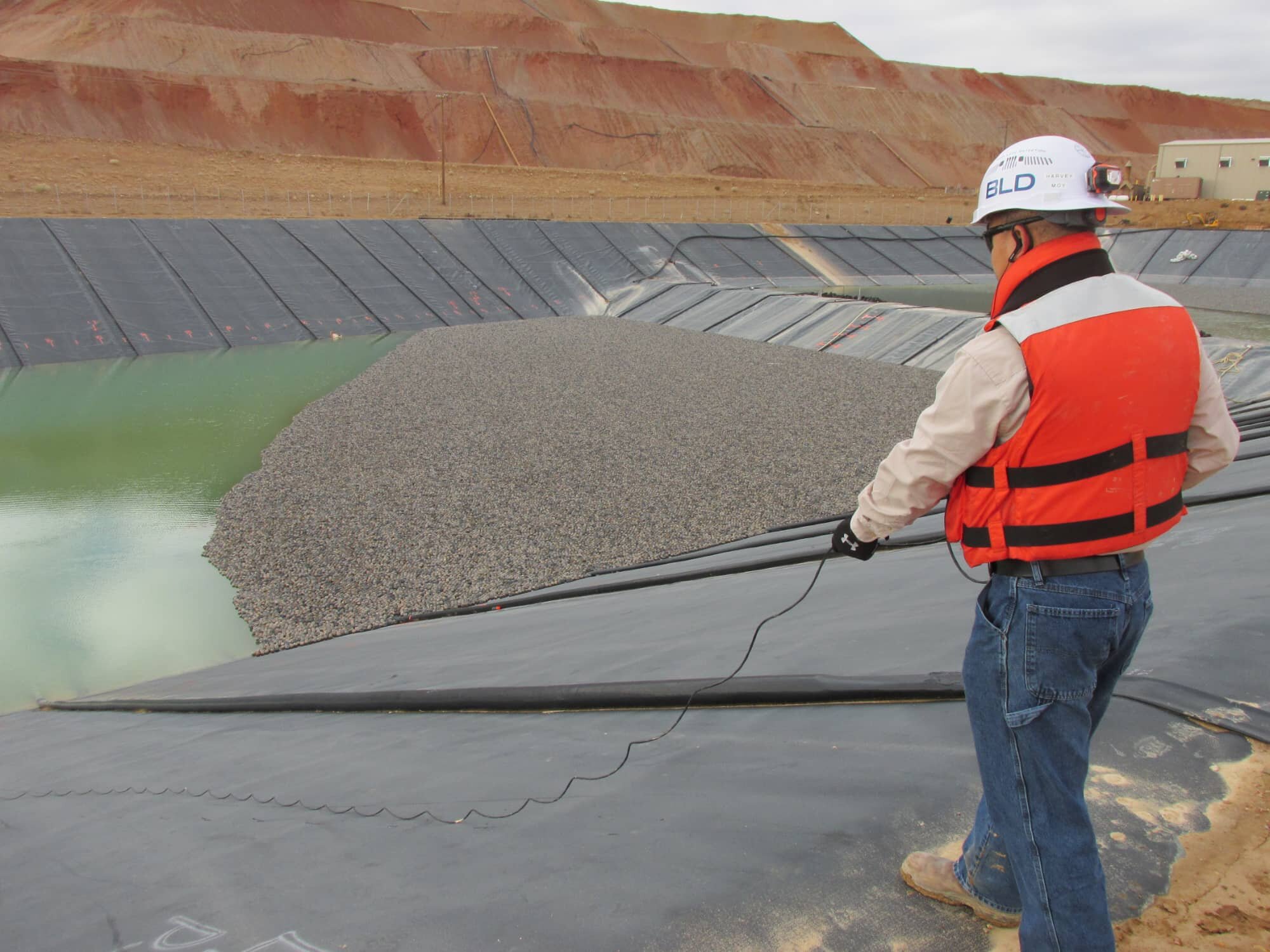
Being the most sensitive water survey, the practicality of this method is obvious when it comes to applications that may contain layers of sediment. May also be known as the "Drag Probe Method", this method is widely performed and is highly recommended for containment ponds, brine ponds, or leachate ponds. During the survey, a technician and an assistant would stand on opposite banks of the application and drag a probe across the floor area and side slopes. The distance to the leaks are measured according to the measurement labeling system on the probe cord. They are documented on the side slopes with a location and reference mark. This is the most popular and preferred method for any pond, lagoon or reservoir filled with liquid.
depth is too shallow to maintain a minimum depth level of
3 in (8 cm)
covered until the pinpoint and repair process is complete
See our Preparations and Requirements Guide for General Contractors prior to an on-site leak detection service.

PREP Guide Single-Lined Systems

PREP Guide Double-Lined Systems
Click to view our Specifications Guide for the Electrical Leak Detection Quality Assurance Program using this method.

SPEC Guide Single-Lined Systems

SPEC Guide Double-Lined Systems

Service ID
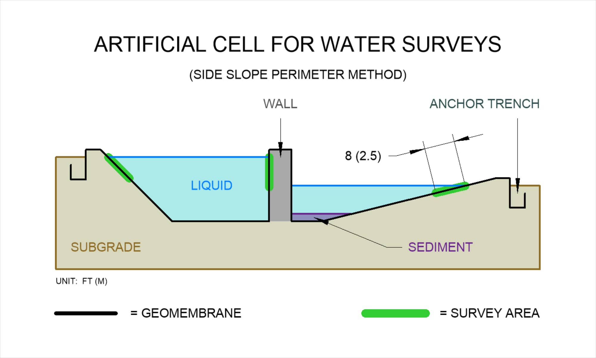
D7007 - SIDE
Side Slope Perimeter
COVERAGE
DESCRIPTION
REQUIREMENTS
DOWNLOADS
Side slopes and vertical walls with approximately 8 ft (2.5 m) of water-covered geomembrane along the perimeter of the application
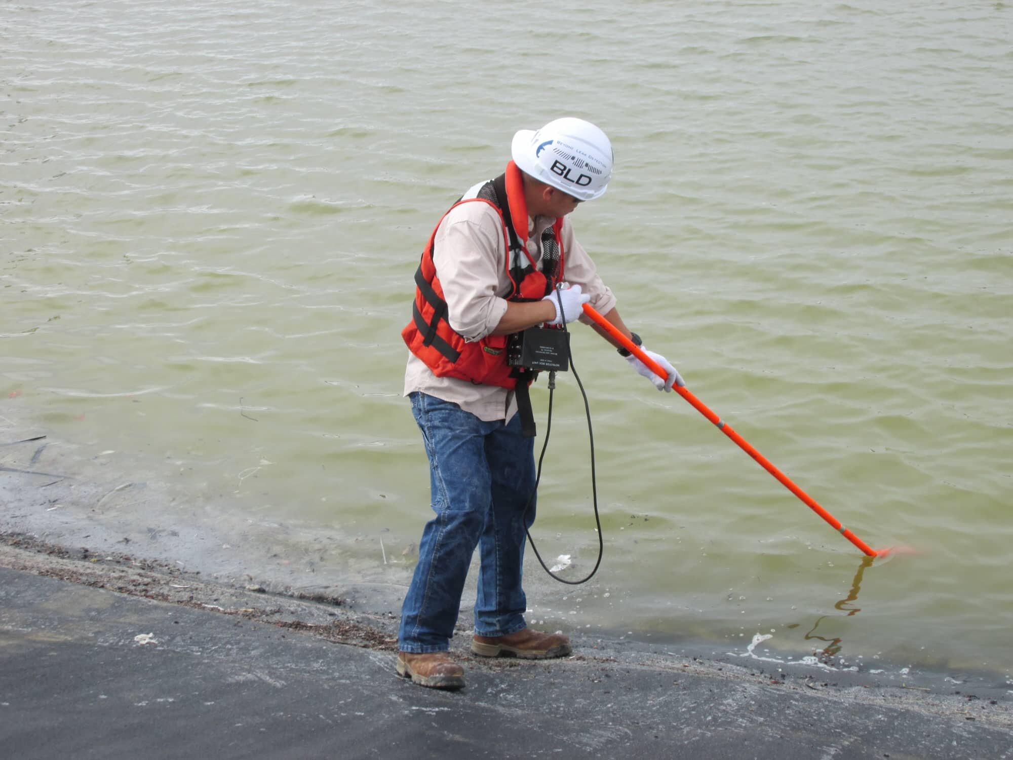
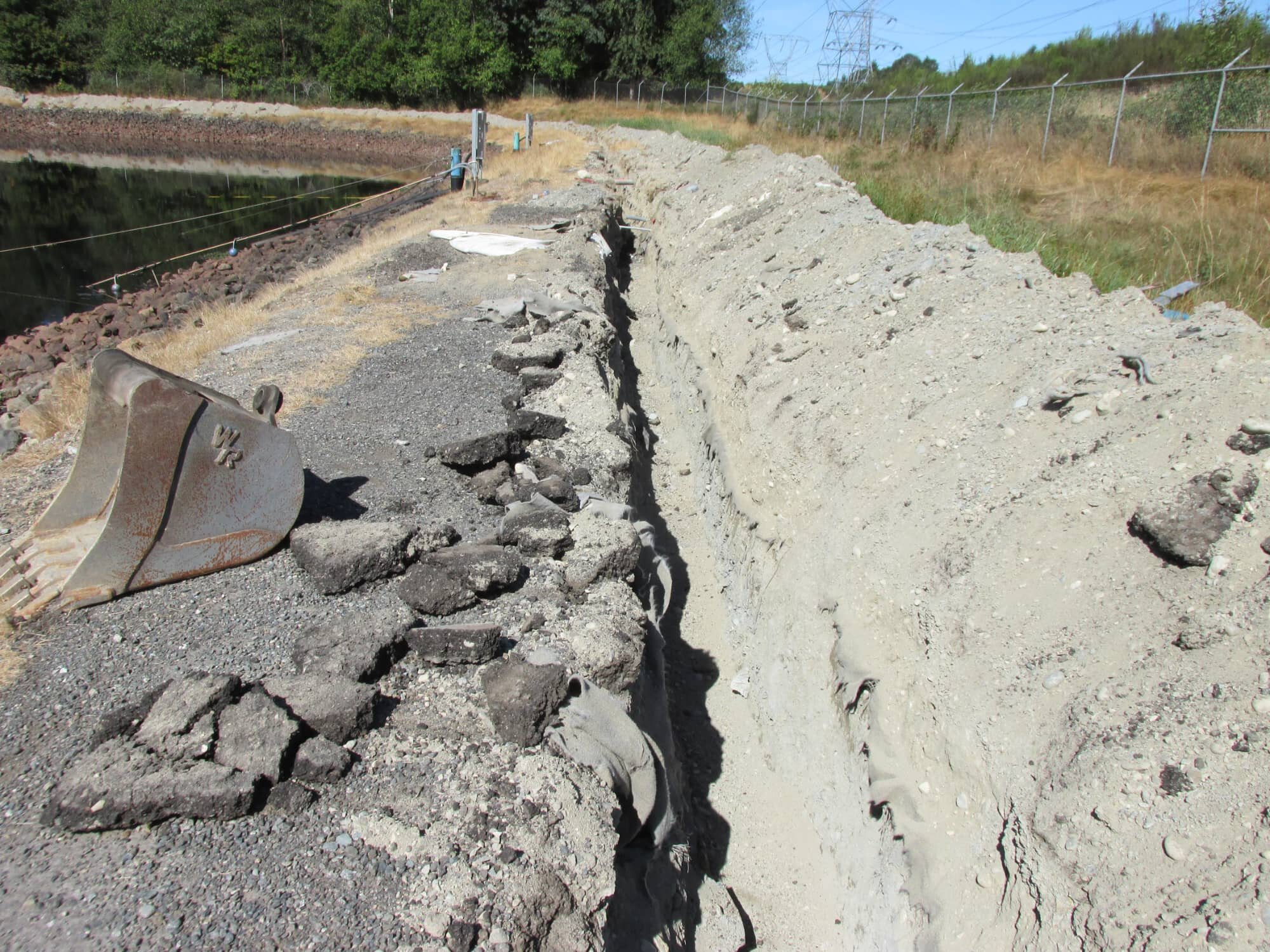
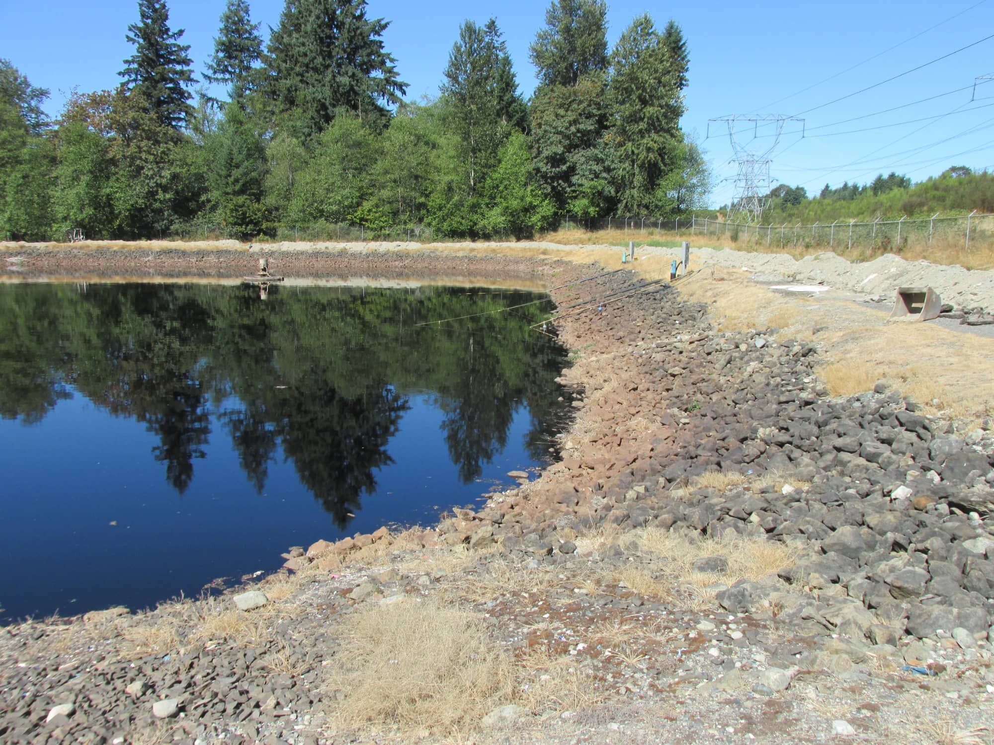
While filling up a containment pond or a pump station vault, some Clients notice liquid in the LDZ immediately which may signify a suspect leak along the side slopes or walls. For this situation, the Side Slope Perimenter Method would be the best option for locating the suspect leak. Similar to a Shallow Water Wade Survey, a technician would use a probe stick to survey the application but only along the perimeter. When a leak is detected, the location is measured with the probe stick and is documented either along the side slopes of the application or on the surface of the containment wall. Since the area of survey is limited to the perimeter of the application along the side slopes or walls, this method tops the list as being the most economical and cost-effective water survey for side slopes.
(2.5 m) from the edge of the liquid solution around the
perimeter of cell
submerged
covered until the pinpoint and repair process is complete
See our Preparations and Requirements Guide for General Contractors prior to an on-site leak detection service.

PREP Guide Single-Lined Systems

PREP Guide Double-Lined Systems
Click to view our Specifications Guide for the Electrical Leak Detection Quality Assurance Program using this method.

SPEC Guide Single-Lined Systems

SPEC Guide Double-Lined Systems
Click to view >

BEST IN WATER SURVEYS
"Most Accurate Survey Method For
Side Slopes"

Click to view >
Service ID
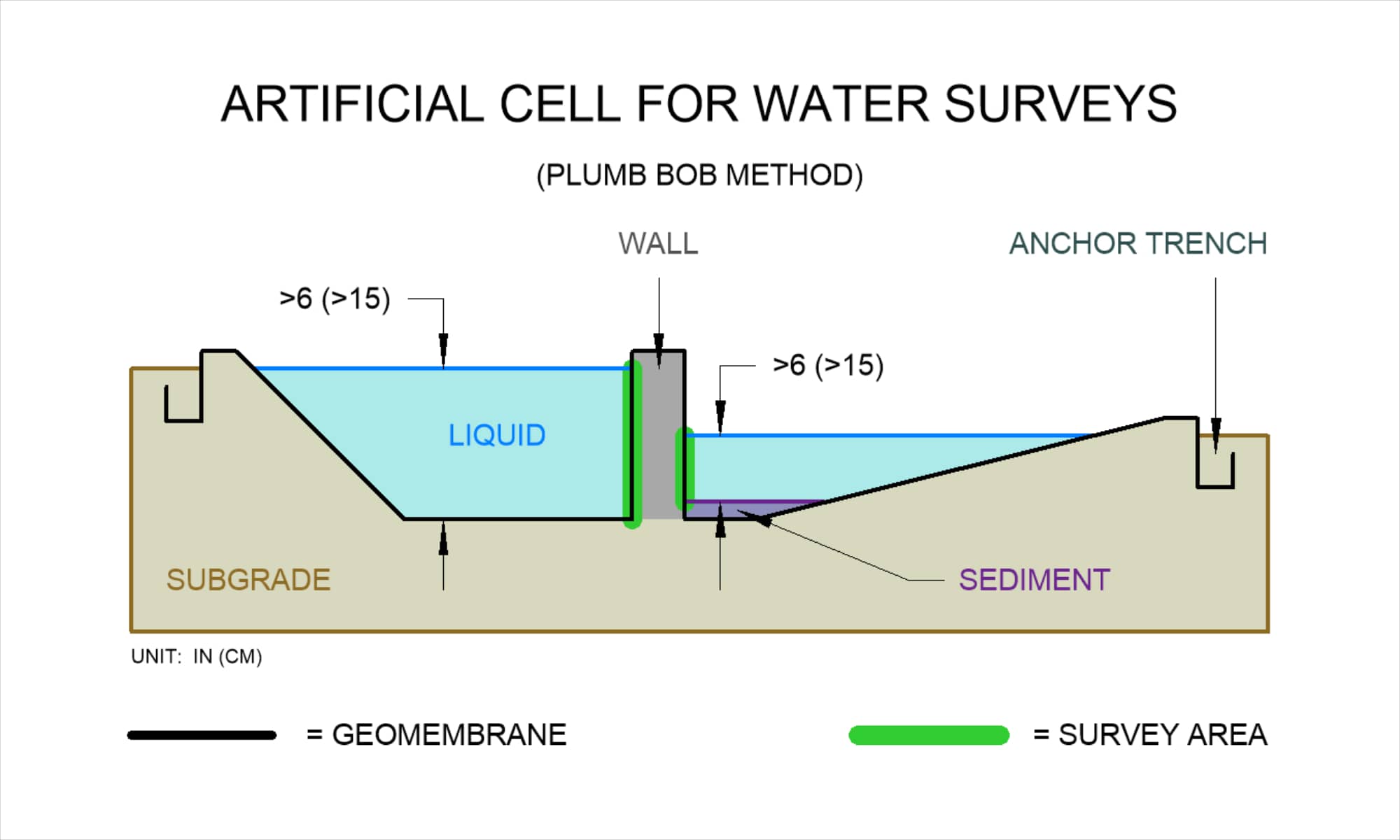
D7007 - PBOB
Plumb Bob
COVERAGE
DESCRIPTION
REQUIREMENTS
DOWNLOADS
Vertical walls with at least 6 in (15 cm) of water-covered geomembrane along the sidewall of the application
Geomembrane-lined walls from containment tanks, channels, dams, reservoirs, or vaults can easily be surveyed using the Plumb Bob Method. A technician would stand near the sidewall and drop a probe along the wall until it reaches the floor. Then the technician would transition to the next survey line and pull the probe back up along the wall as well. The anomaly number and distance to the anomaly will be documented on the sidewall and will be measured via the measurement system on the probe cord. The Plumb Bob Method is budget friendly and has minimal requirements and preparations from the Client.
covered until the pinpoint and repair process is complete
(15 cm) of sidewall liquid covering the geomembrane
See our Preparations and Requirements Guide for General Contractors prior to an on-site leak detection service.

PREP Guide Single-Lined Systems

PREP Guide Double-Lined Systems
Click to view our Specifications Guide for the Electrical Leak Detection Quality Assurance Program using this method.

SPEC Guide Single-Lined Systems

SPEC Guide Double-Lined Systems
* Recognitions are based on gathered information and data collected since 2010 when compared to other survey methods provided by BLD.

