

The Geoelectric Leak Detection Methodology
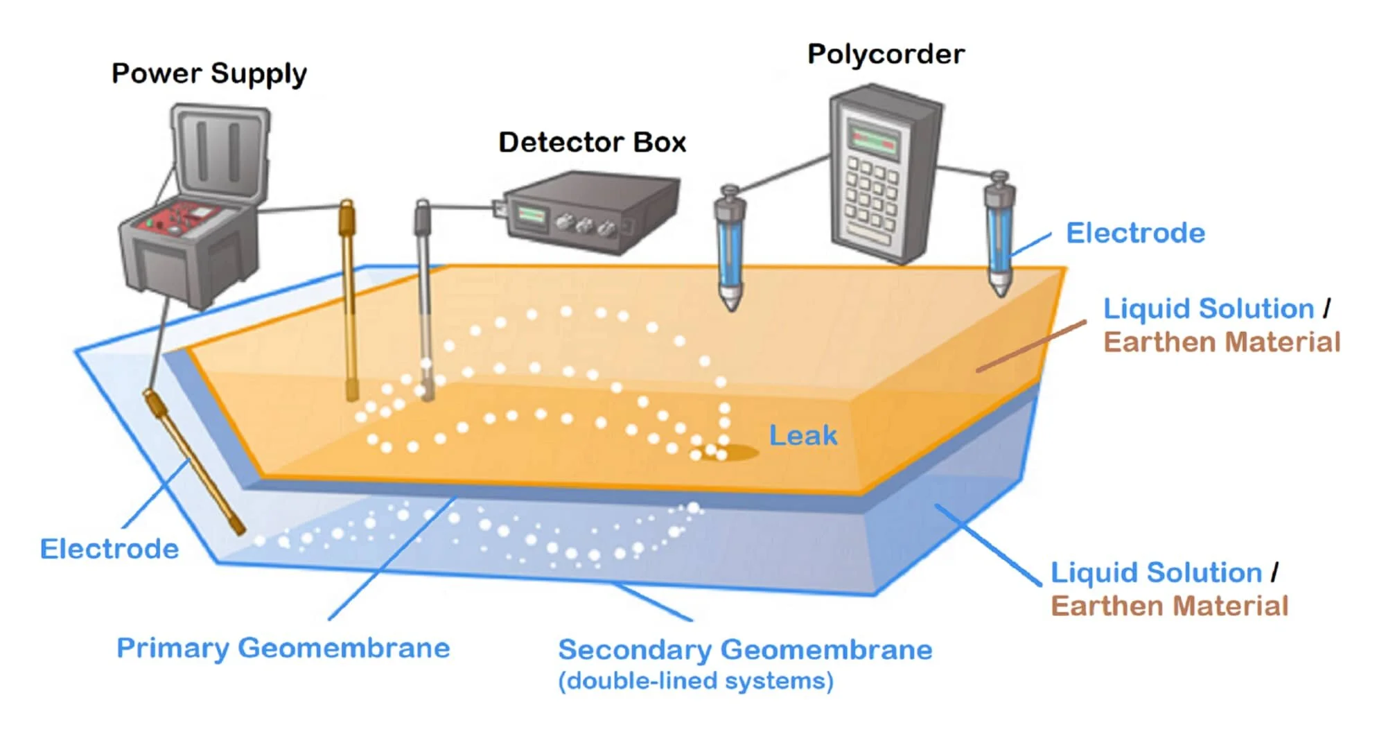
Electrical leak detection methods implement a physical, real-world circuitry consisting of electromagnetic fields and current density. The relative geomembrane, or the top-most liner that will be tested for integrity, penetrations or leaks, acts as an electrical insulator and emulates a current barrier. The low permeable membrane prevents electrical connection between the medium (liquid solution/earthen material) covering the liner and beneath the relative geomembrane when the application is energized via current electrodes.
When the application or impoundment has been energized and saturated, localized ripple-effects of high current density only occur in areas where the medium above and below the relative geomembrane are making electrical contact or connection. These areas of connection, or anomalies, provides differential voltages due to the resistance in size and shape. Potential measurements are collected near these areas via custom-made leak detection probes and equipment. The measurements are translated into a visual graph when collecting data on earthen materials, or through a high frequency audible tone when performing a water or bare-liner survey. Once the general location of the anomally has been investigated, the excavation of material or removal of liquid may begin to pinpoint the anomally or leak signal.
Key Preparations and Requirements
A very important aspect for an efficient leak detection service would be the preparations required prior to a confirmed project mobilization. Support during the leak detection process would effectively target an on-time schedule for project completion. Therefore, it is essential that critical preparations and support are provided from the Client to minimize any unexpected delay time. Some key preparations and requirements are noted below.
SATURATION For landfills, containment systems, and surface impoundments that have a geomembrane covered with soil or earthen materials, wetting of all the layers on top of the geomembrane in uniform during installation of the geosynthetic system will minimize resistance to the leaks and increase electrical connection. If the layers above the geomembrane are dry, then the layers will simulate an electrical barrier or isolator minimizing the leak detection sensitivity. These dry areas or unsaturated voids may imitate and portray a characteristic leak signal during analysis and thus, may create a false positive. Therefore, pre-wetting these layers are essential for the leak detection process.
ELECTRICAL ISOLATION A temporary electrical isolation trench or channel throughout the entire perimeter of the application is required to prevent current from traveling to earth ground which may result in false positives. In addition, to effectively increase the leak detection sensitivity, any connections to earth ground such as ramps or conductive pipes must be removed or disconnected. An electrical isolation trench consists of an area of exposed geomembrane that separates the material covering the liner and the material either beneath the geomembrane or the surrounding earth ground. Excavating the isolation channel to a width of approximately 6 to 24 in (15 to 60 cm) will be sufficient. The electrical isolation trench is mainly applied to single-lined systems. However, for double-lined systems, if the underlying or secondary geomembrane has never been tested, it is highly recommended that the excavation of this trench is also performed to ensure electrical isolation.
DISPLACEMENT Double-lined systems with liquid mainly contain an installed geotextile, geonet, geogrid, or geocomposite between the geomembranes. One key element when performing water surveys is achieving zero displacement. Zero displacement is recommended (if practical) and must be prepared prior to surveying. This is performed by raising or lowering the level of liquid in between the geomembranes, or leak detection zone (LDZ), to achieve equal water depth with the liquid covering the geomembrane. Any displacement of liquid either on top of the primary geomembrane or in the LDZ may result in anomalies that cannot be detected. The liquid depth in the LDZ must be monitored and maintained constantly to minimize displacement throughout the survey.
WIRE ELECTRODE Even though conductive materials are present during the geosynthetic installation process, the electrical connection to these materials may be cumbersome. Installing an 8-AWG solid, bare-copper wire electrode alleviates the burden in the field for technicians trying to make a sound electrical connection. The electrode must be placed on top of a geosynthetic clay liner (GCL), geotextile, geonet or geocomposite prior to installation of the top-most geomembrane. The wire electrode is required to help ensure electrical connection in between the geomembranes and must not be damaged. In addition, when exiting the geomembranes, the copper wire electrode must not be in contact with earth ground or the material covering the top-most geomembrane or this may result in false leak signals (false positives) that may be present during the leak detection process. Technicians will need to access the wires at all times to conduct a successful survey.
RAMPS During placement of materials over geomembrane when constructing landfills, containment systems, or surface impoundments, the logistics for machinery and vehicles to enter and exit the application may be challenging while a leak detection survey is underway. The temporary contruction of ramps or bridges to enable traffic will be required to maximize efficiency during the construction process. However, electrical isolation is still required at all times while performing the survey especially for single-lined systems. To overcome this obstacle, a geomembrane flap (temporary or permanent) will be required. This is constructed by either welding a geomembrane flap only accross traffic areas (where ramps or bridges are located) or by extending the geomembrane material in the anchor trench throughout the entire perimeter of the application. The exposed geomembrane flap must have these conditions: extend 1 to 2 ft (30 to 60 cm) above the surface for clearance and isolation, have welds when joining geomembranes, not be damaged, and not have any openings such as open seams or holes. To prevent future excavation when an electrical isolation trench is required, installation of the exposed geomembrane flap is highly recommended throughout the perimeter of the application. Installation of this isolation flap may be trimmed down to surface level when the leak detection survey is complete.

