


Monitoring pipes or a containment application may be beneficial in a variety of ways. Even though a vast amount of geomembrane installers are tested through a rigorous quality control and assurance program, a gradual stress may occur throughout the aging process of the liner. In combination with severe environmental conditions, the integrity of the geomembranes may fail when least expected.
In response to these unexpected failures, we have developed an electrical leak monitoring system that contains an array of permanently buried electrodes. This system, or the Permanent Electrical Leak Monitoring (PELM®) System, is a custom-made leak detection system installed in the application for monitoring the integrity of a liner or HDPE pipes via electrodes. The electrodes are installed and used to collect electrical resistance (or potential measurements) under normal operating conditions throughout the life of the application. A web-based or independent leak detection monitoring software is easily accessible to Clients making it convenient to determine the locations of leaks using the program.
SYSTEM FEATURES
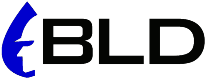
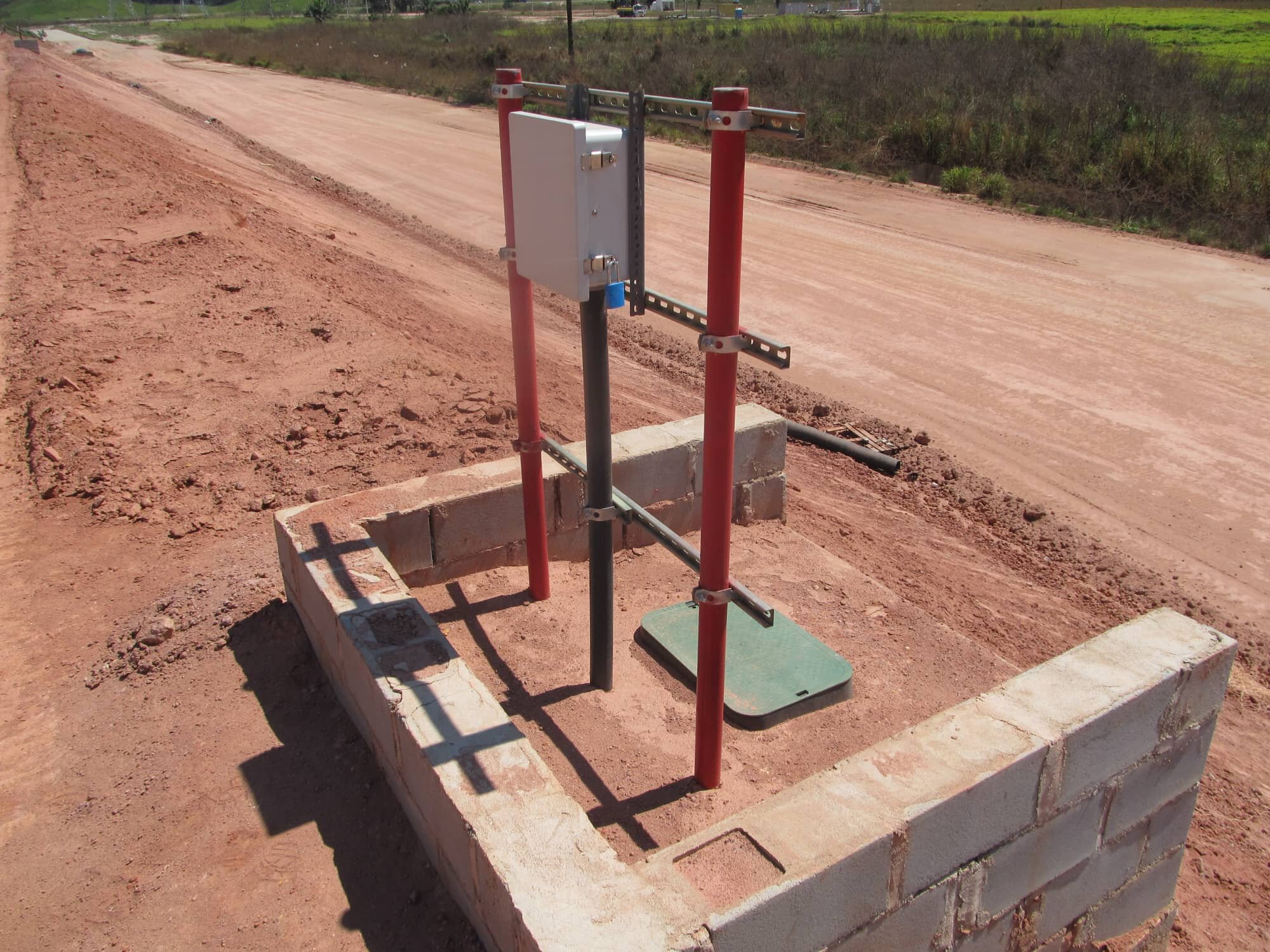
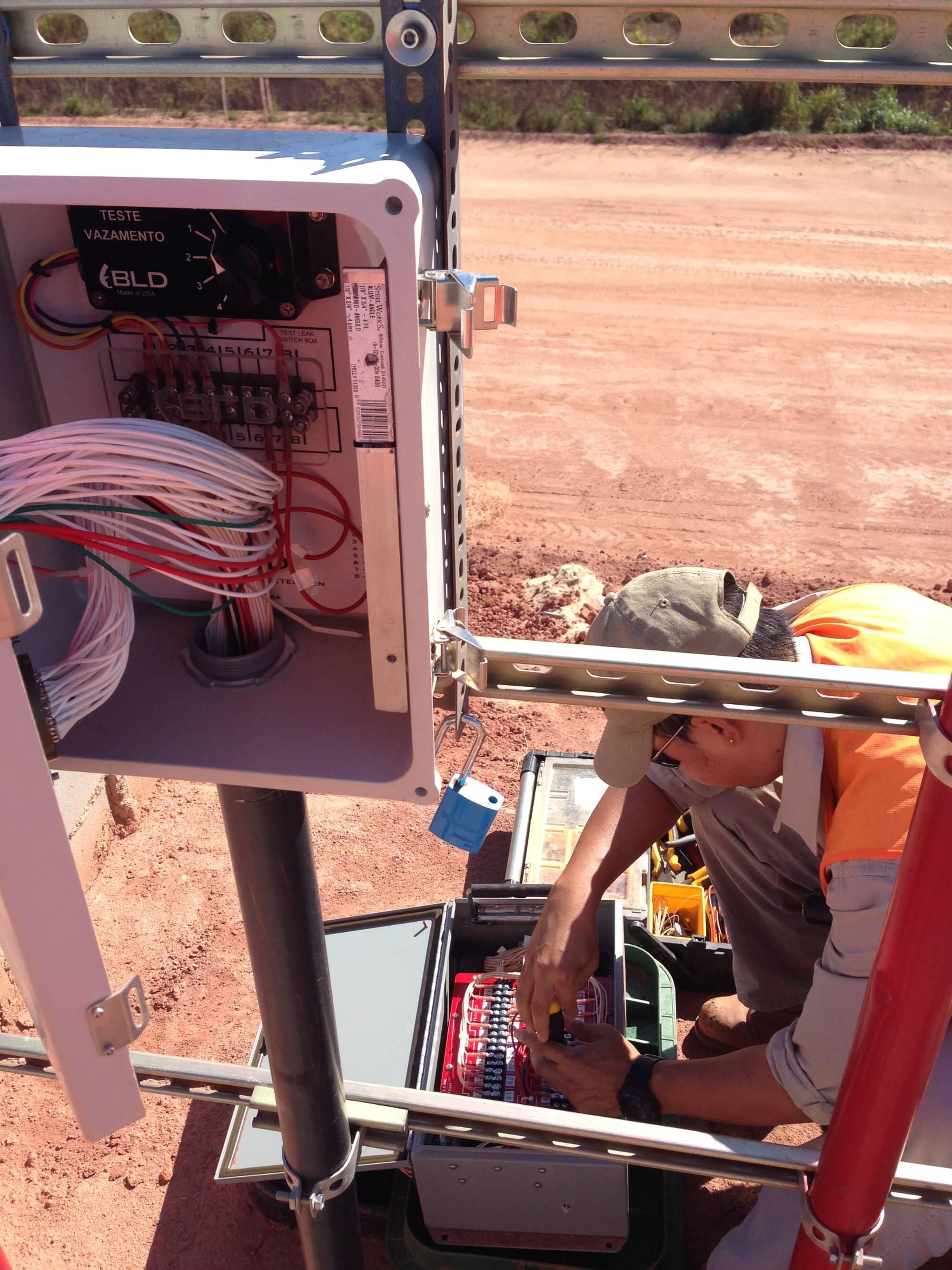
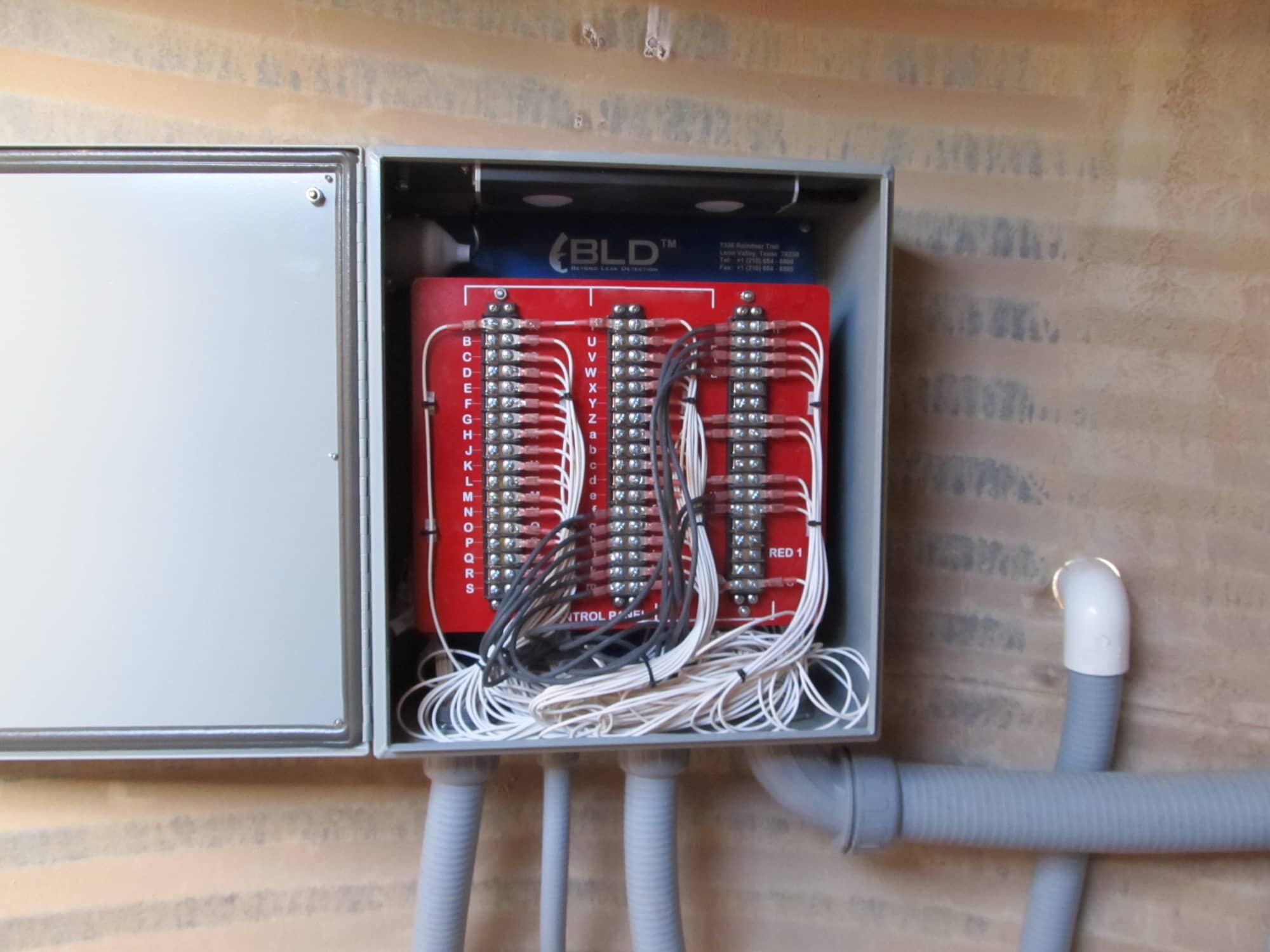
CONTROL PANELS
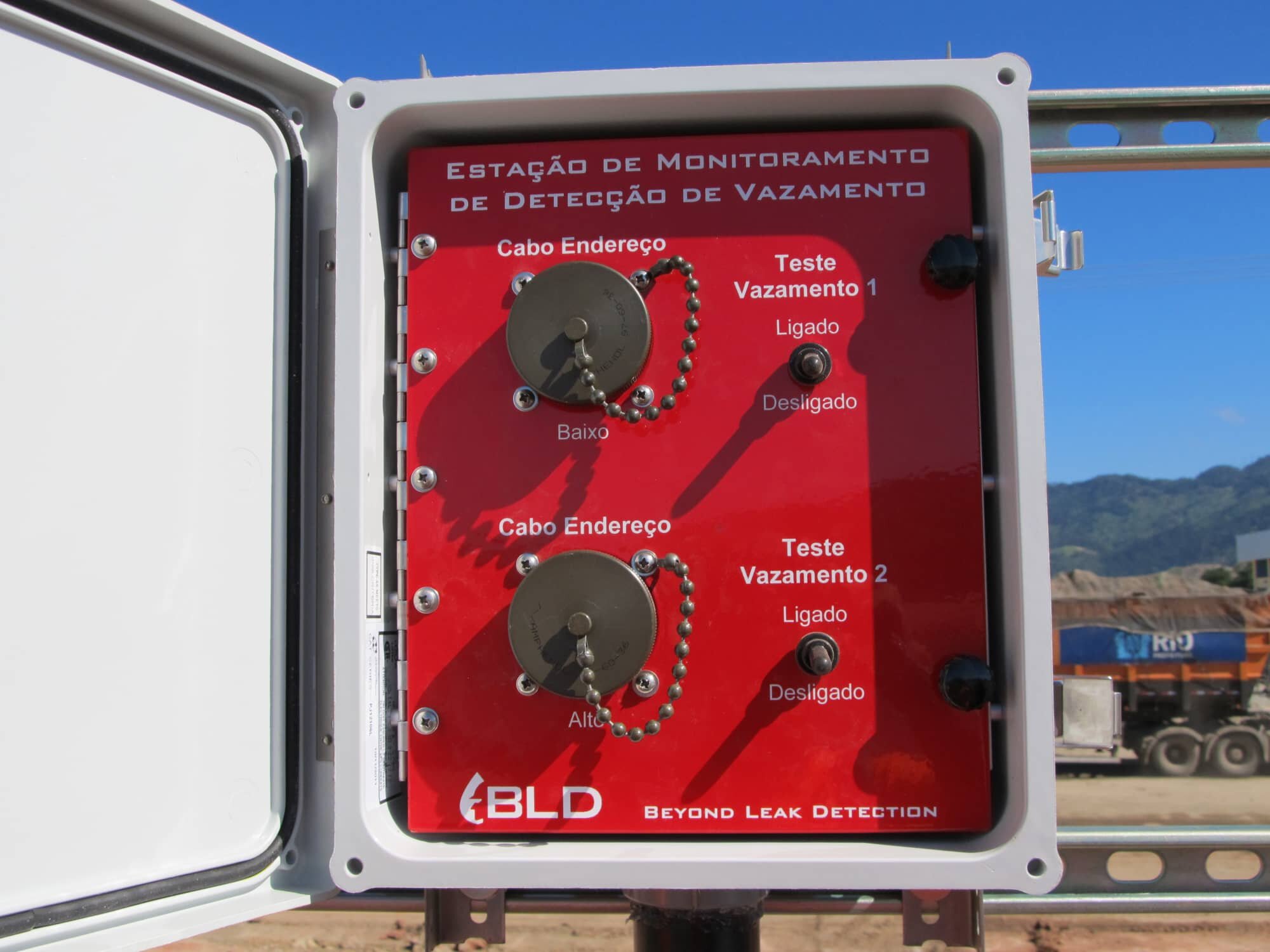
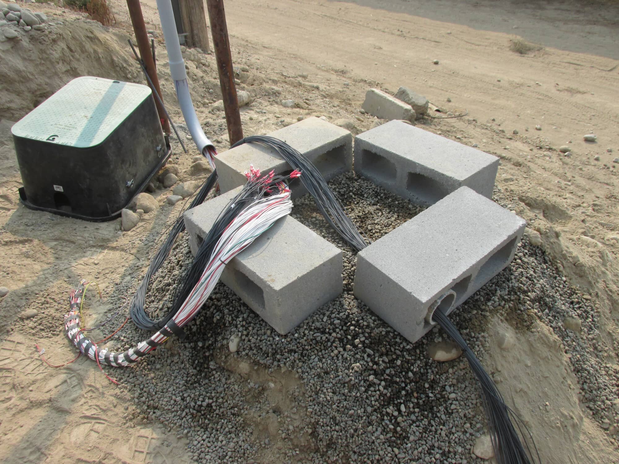
JUNCTION BOXES
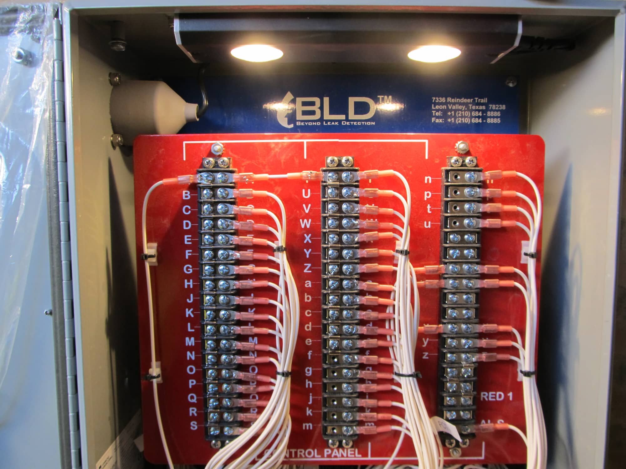
TEST LEAK UNITS
CURRENT ELECTRODES

Control panels are custom designed and made per Client requirements and specifications. A control panel can access up to a maximum of 96 measurement electrodes.
POTENTIAL ELECTRODES

Disconnect Junction (DJ) boxes provide reassurance when control panels are located in high traffic areas or where damages to the control panel may occur due to unexpected accidents.
RESISTIVITY METERS

To verify the monitoring system is working correctly and to check the leak detection sensitivity of the system, the Artificial Test Leak Unit is installed with simple, user-friendly controls.
SOFTWARE APPLICATION

Different types of Source and Reference Electrodes are available and provide multitudinous purposes for the system. They are the main elements when energizing the application.
POWER SOURCE

Sensor and Artificial Leak Electrodes are installed throughout the application for measuring voltages and calibrating the system. These stainless steel electrodes provide outstanding resistance to rust and oxidation.

Resistivity meters are the main components in data collection. These meters are connected to the control panel, and the survey is conducted through command files that operate the meters.

A custom-made leak detection software analysis program is created per project application and specification. The software is analyzed online with or without GPS-based coordinates and will notify Clients if a potential or suspect area of concern requires investigation.

Powering the PELM® System requires a portable, marine, 12-Volt deep-cycle battery that must be recharged after a full day of usage.

PELM® System Installation for
Water Containment Systems
Service ID
PELMI - WATR
DESCRIPTION
ORIENTATION
SOFTWARE
ARRAY FORMAT
REQUIREMENTS
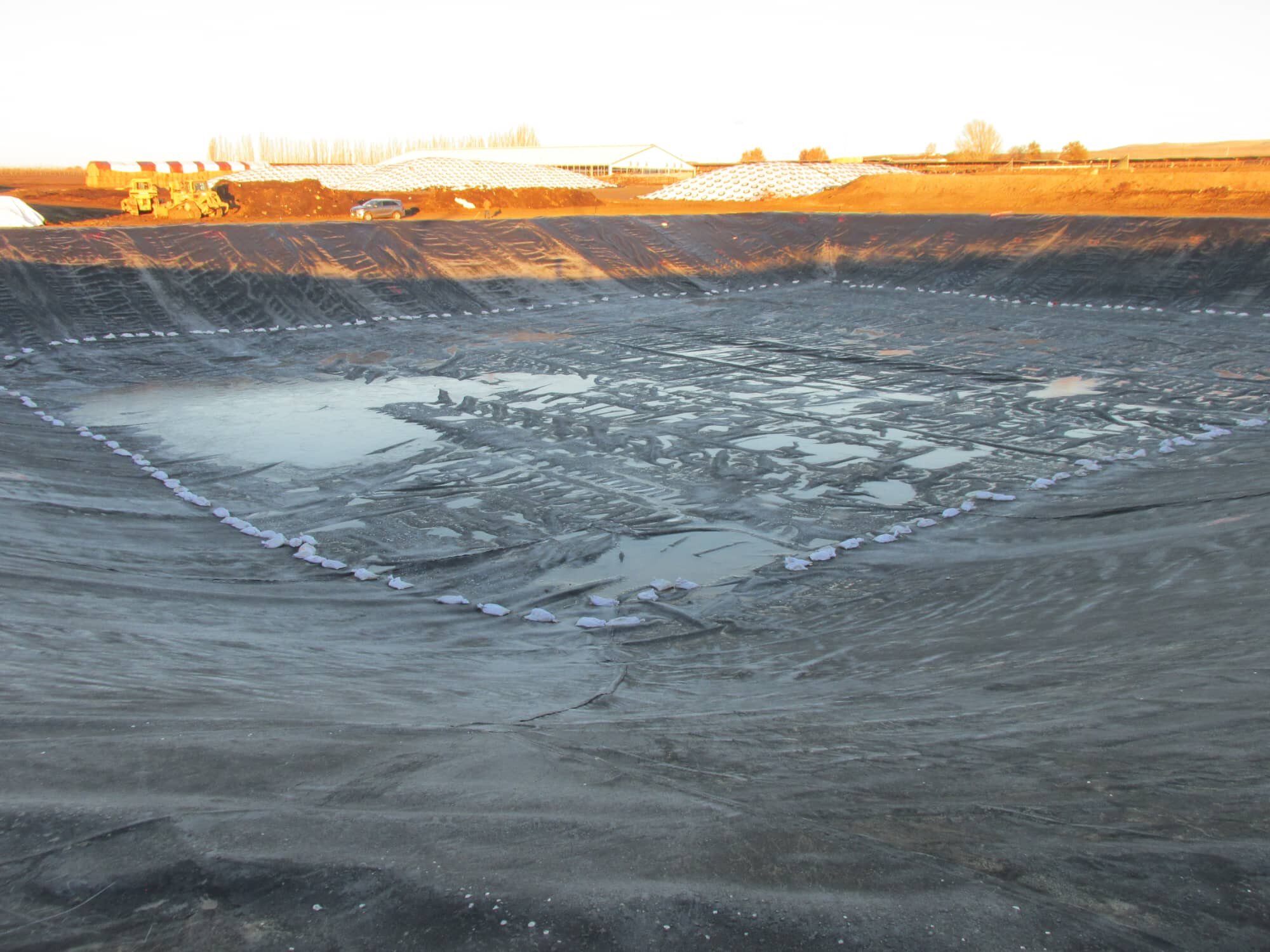
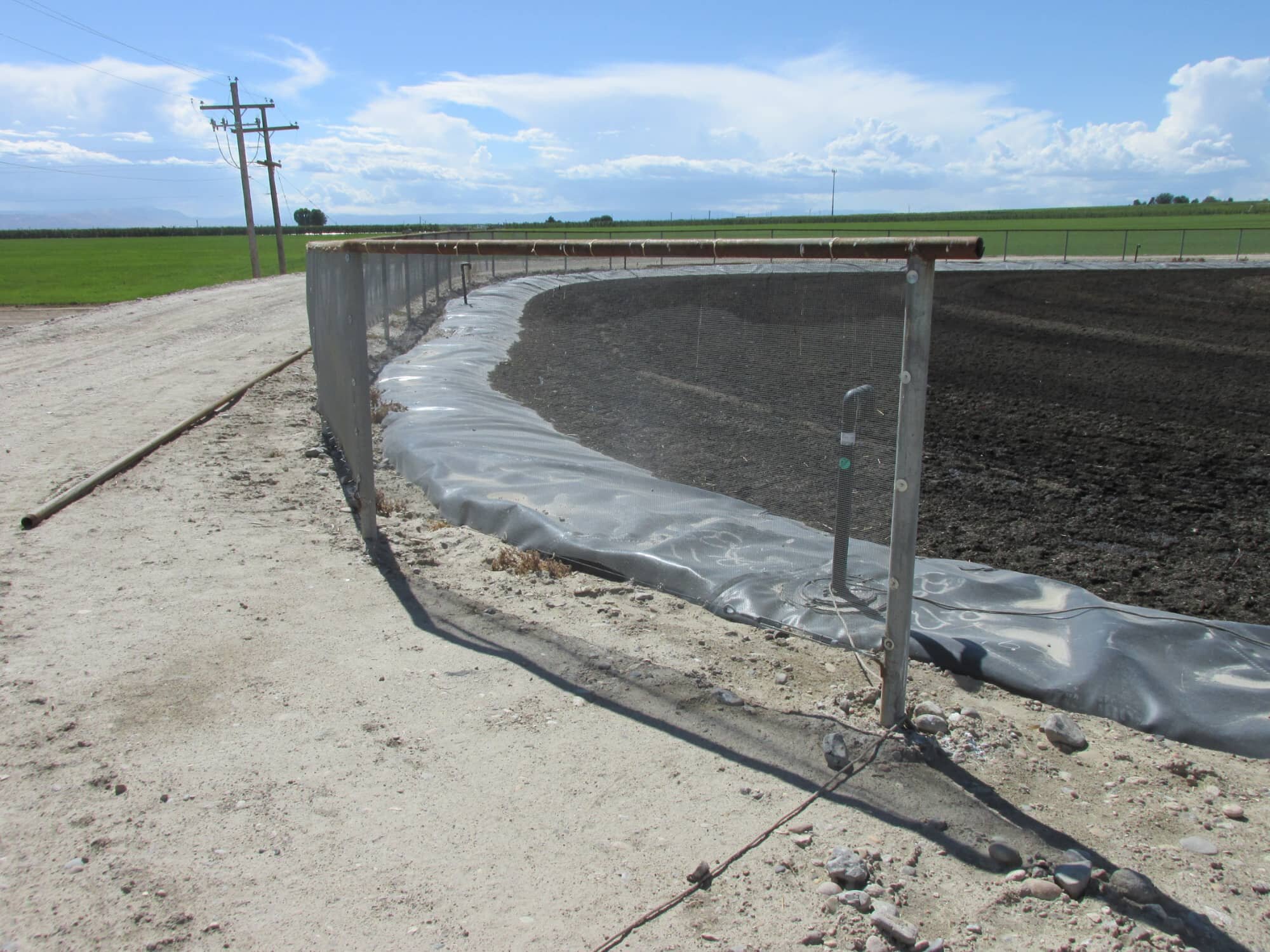
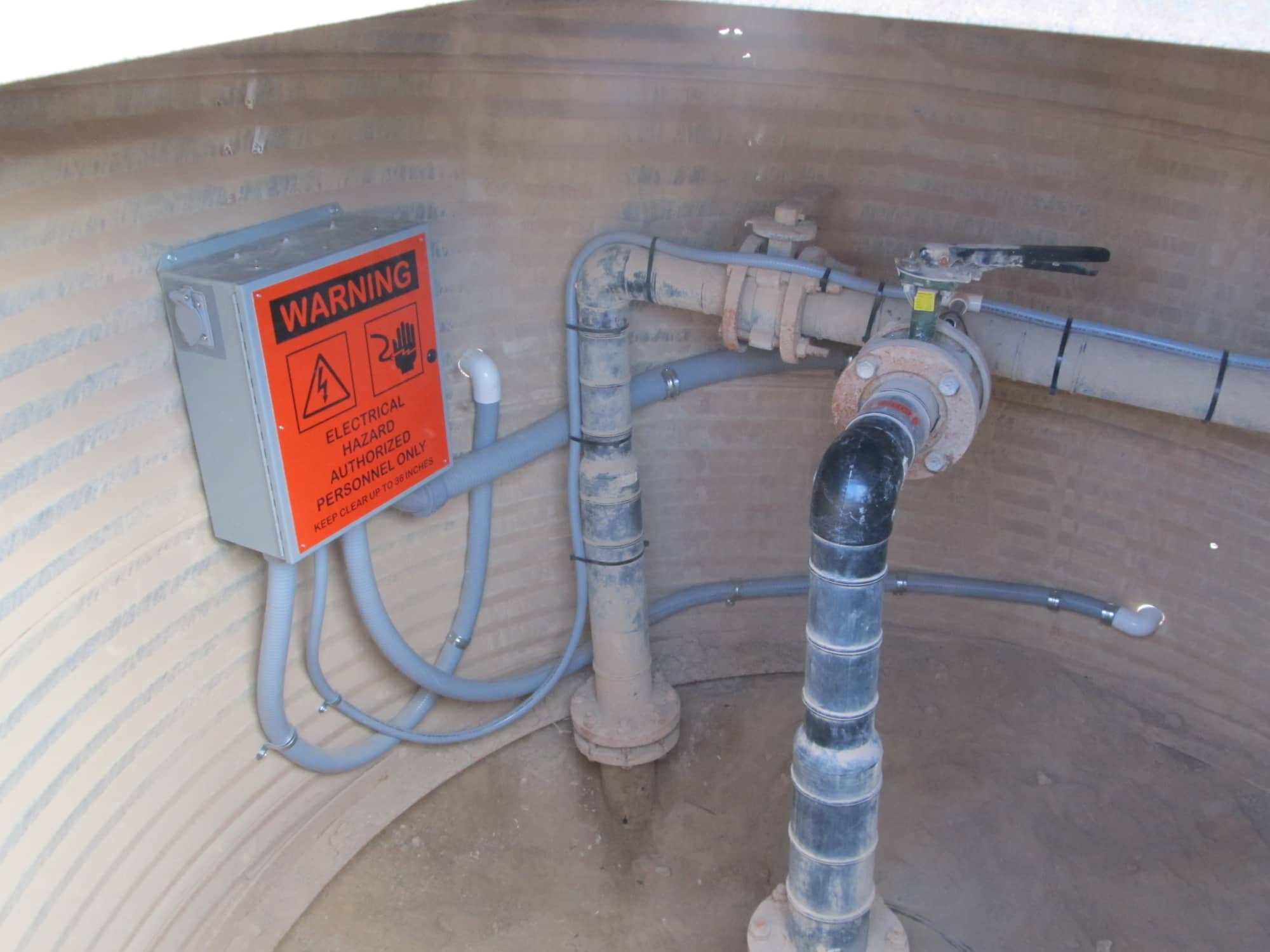
Containment systems for liquid are among the hazardous containment appplications that may require full-scale decontamination for equipment and personnel. Instead of physically surveying the application and risk contamination, another option would be to install a monitoring system and monitor the application from a control or measurement station. Installing a PELM® System for a water contaiment system such as lagoons, ponds, or reservoirs, can be greatly beneficial especially when monitoring the integrity of a geomembrane over a lengthy period of time. This is developed by installing potential and current electrodes throughout the entire application. Potential electrodes are spaced equidistantly in an array format with a XY coordinate system orientation. Once all the elements of the PELM® System has been installed, calibration of the system is performed, training is provided, and a final PELM® Survey is conducted. The PELM® System for water containment systems can monitor the life of the application at various frequencies per Client requirements and elinimates the chance of hazardous contact with personnel.
XY-Matrix Coordinate System
2-Dimensional Matrix Configuration
installation of wires and electrodes
liquid depth of 6 in (16 cm)

PELM® System Installation for
Soil Containment Systems
Service ID
PELMI - SOIL
DESCRIPTION
ORIENTATION
SOFTWARE
ARRAY FORMAT
REQUIREMENTS
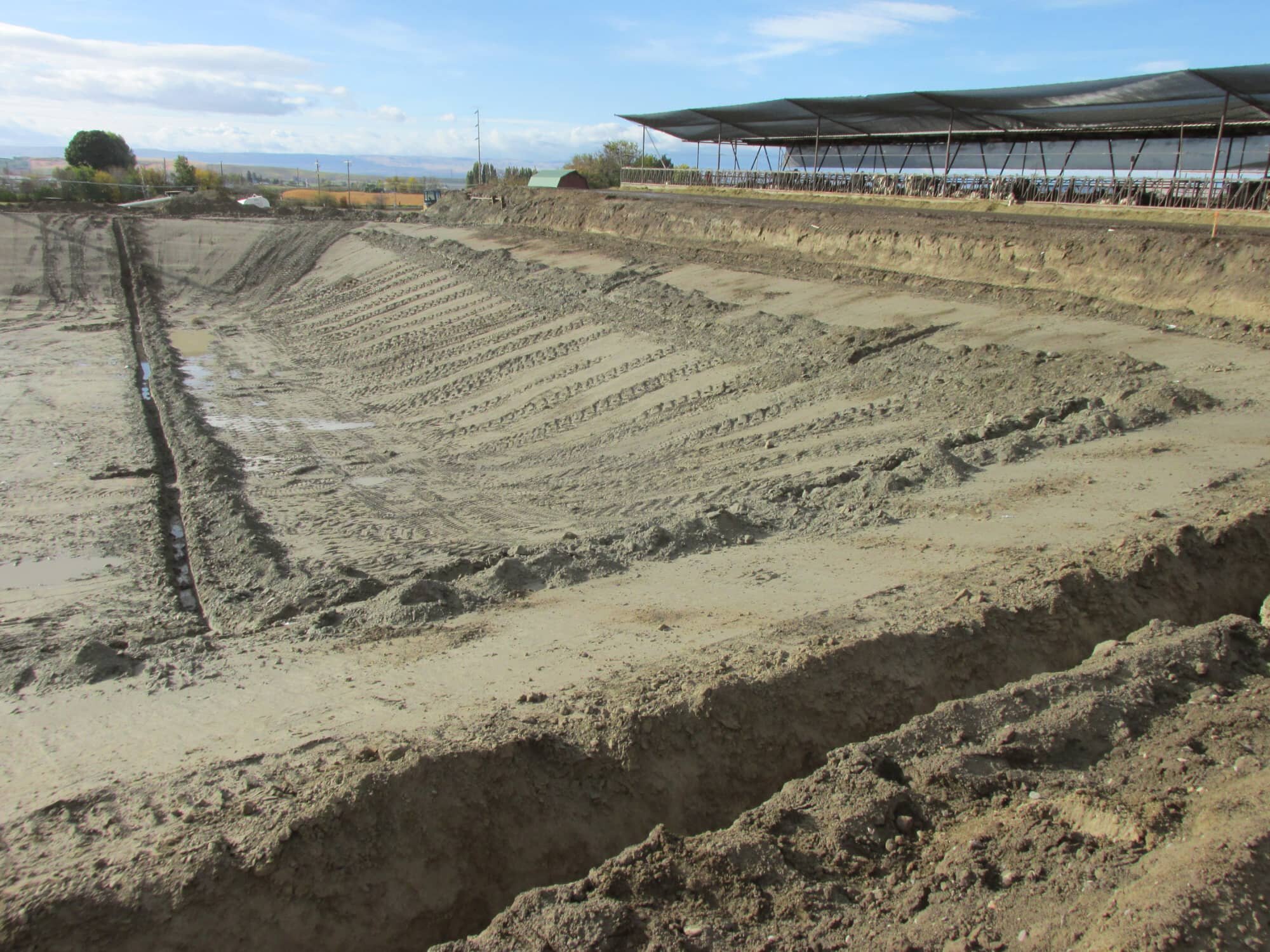
Protecting the environment by minimizing or even eleminating contaminated elements that may potentially contain hazardous substances is a safety concern second to none. Installing a PELM® System for a soil contaiment system such as landfills can be greatly beneficial especially when monitoring the integrity of a geomembrane over a lengthy period of time. This is developed by installing potential and current electrodes throughout the entire application. Potential electrodes are spaced equidistantly in an array format with a XY coordinate system orientation. Once all the elements of the PELM® System has been installed, calibration of the system is performed, training is provided, and a final PELM® Survey is conducted. The PELM® System for soil containment systems can monitor the life of the application at various frequencies per Client requirements.
XY-Matrix Coordinate System
2-Dimensional Matrix Configuration
installation of wires and electrodes
soil depth of 6 in (16 cm)


Featured Project

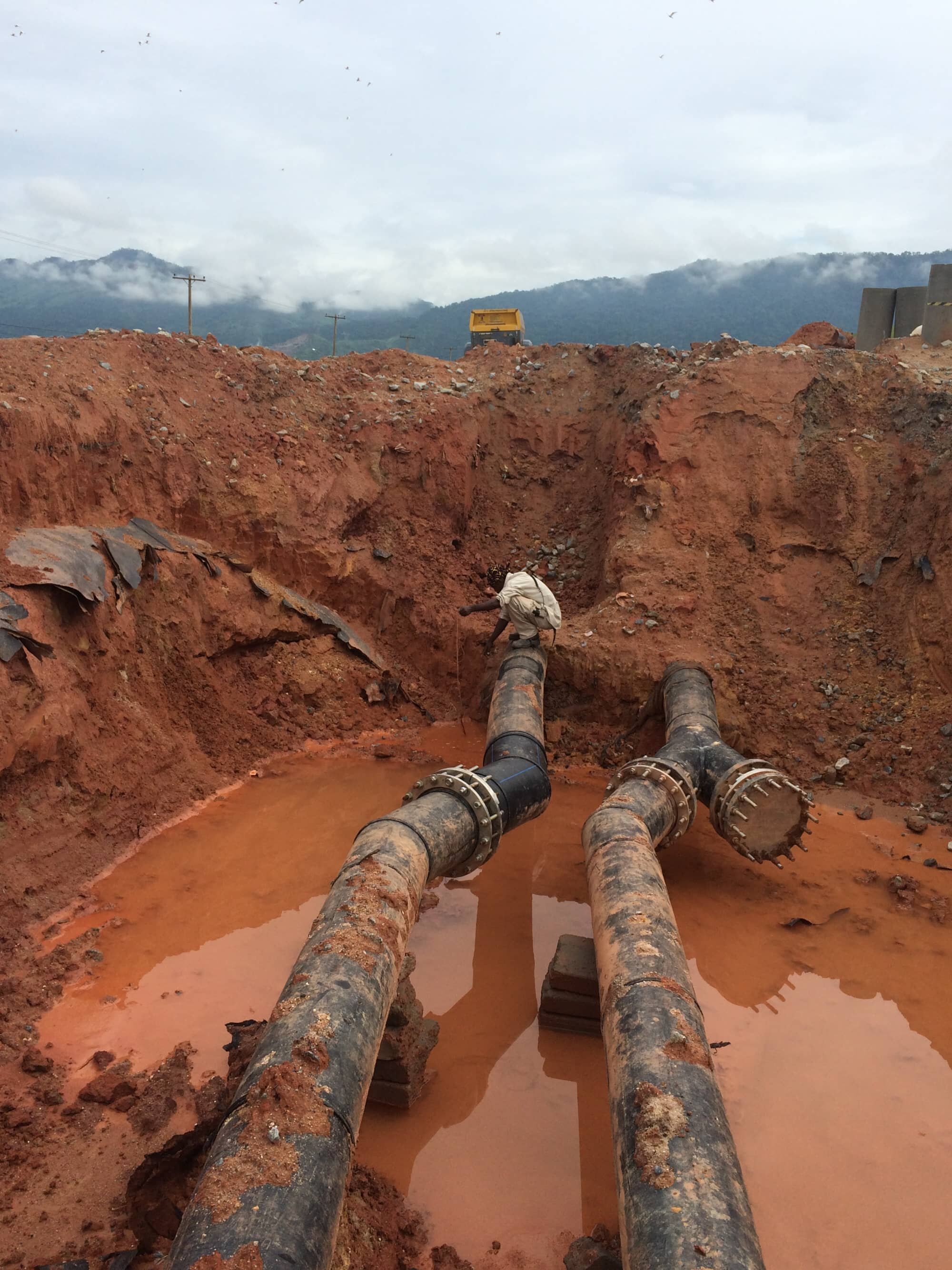
PELM® Sytem Installation for
Nonconductive Buried Pipes
Service ID
PELMI - PIPE
DESCRIPTION
ORIENTATION
SOFTWARE
ARRAY FORMAT
REQUIREMENTS
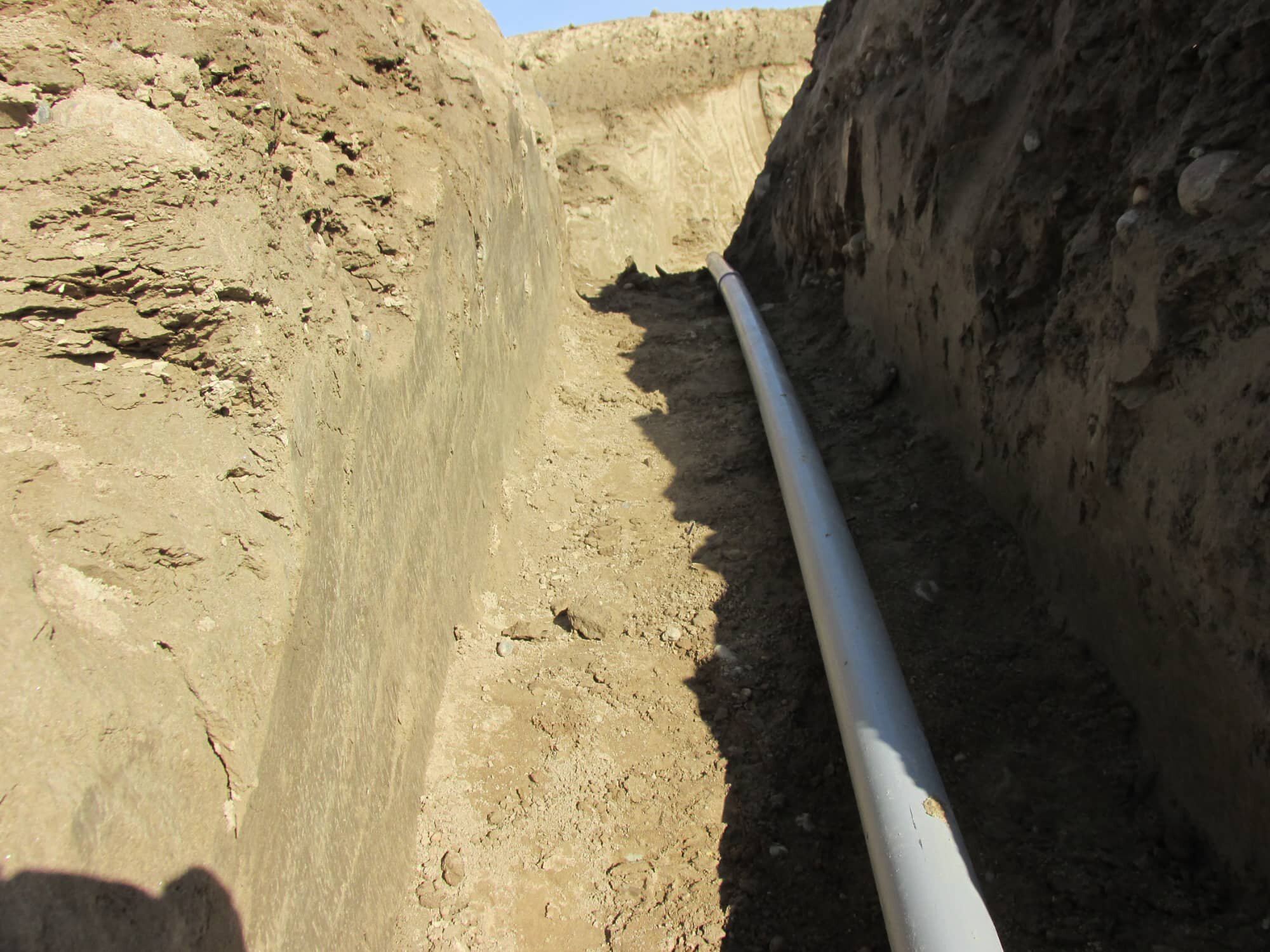
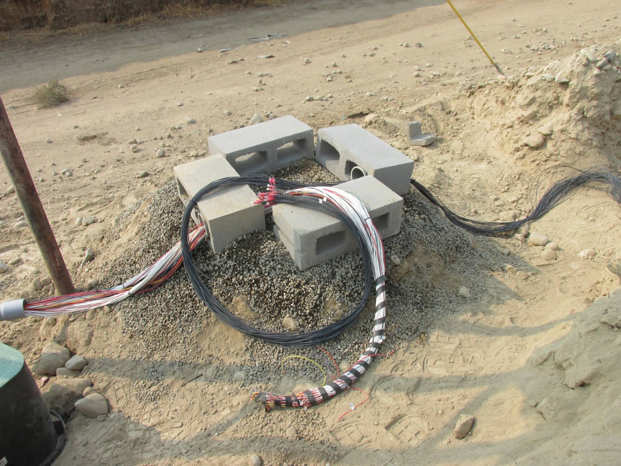
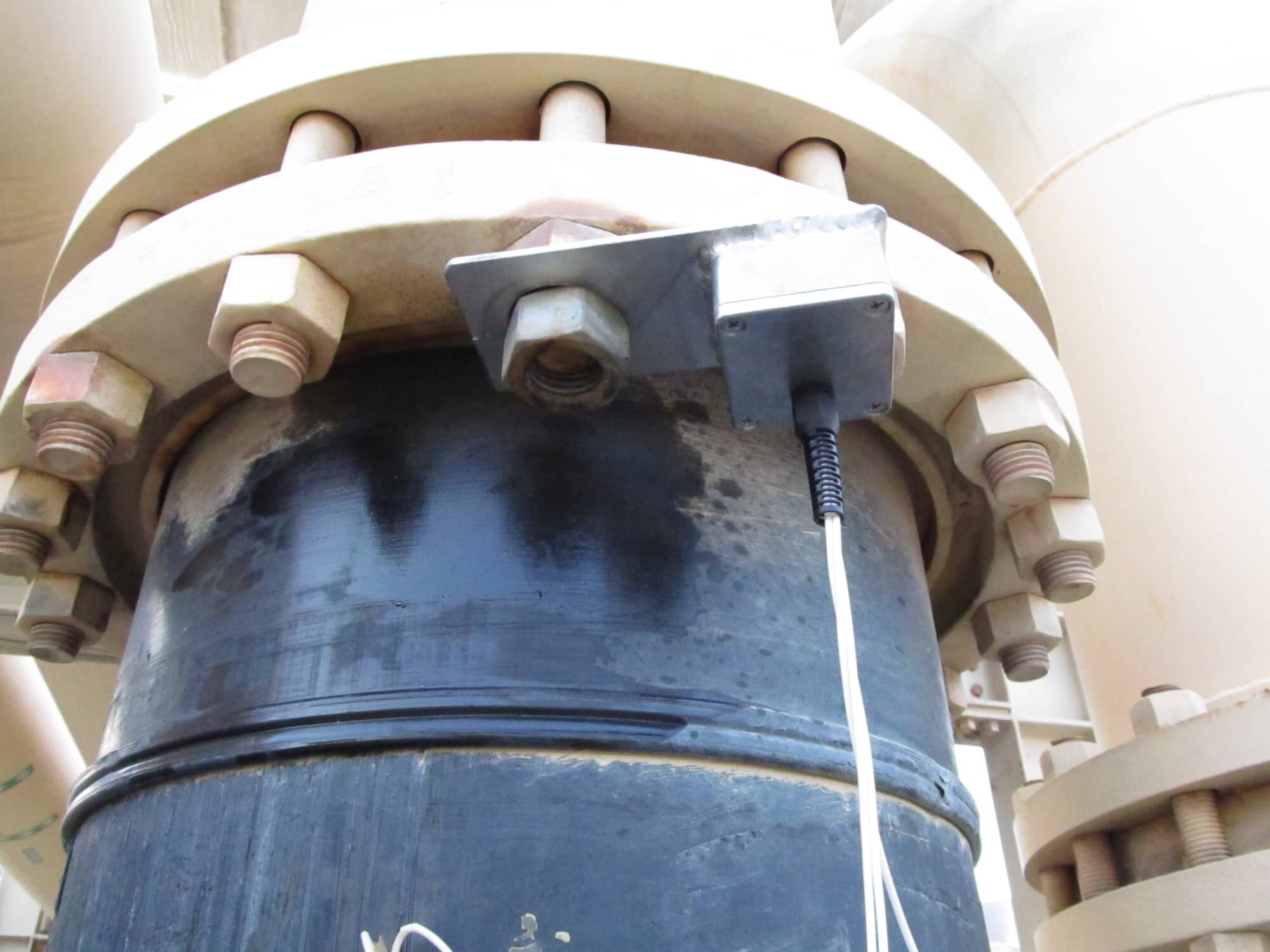
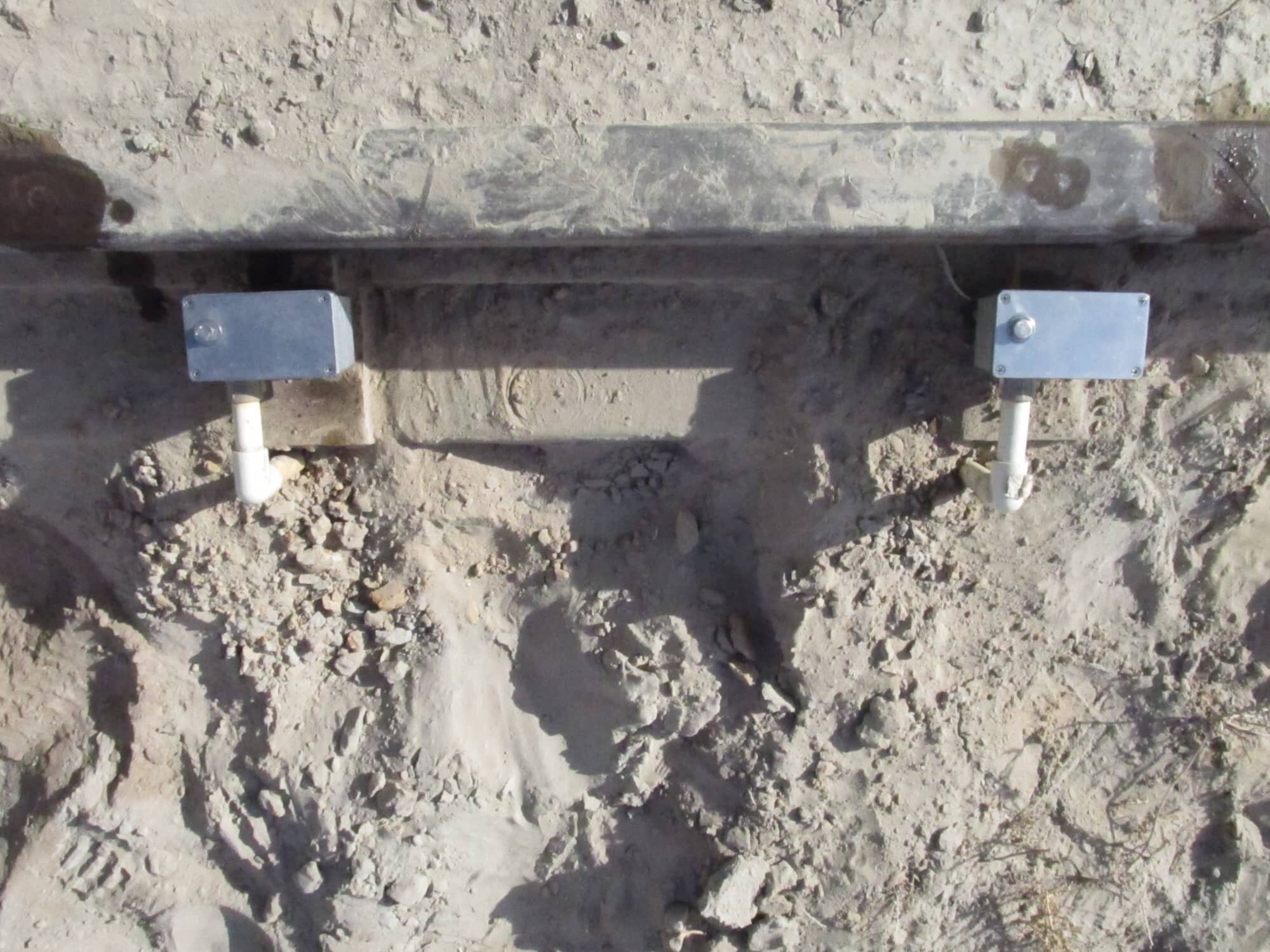
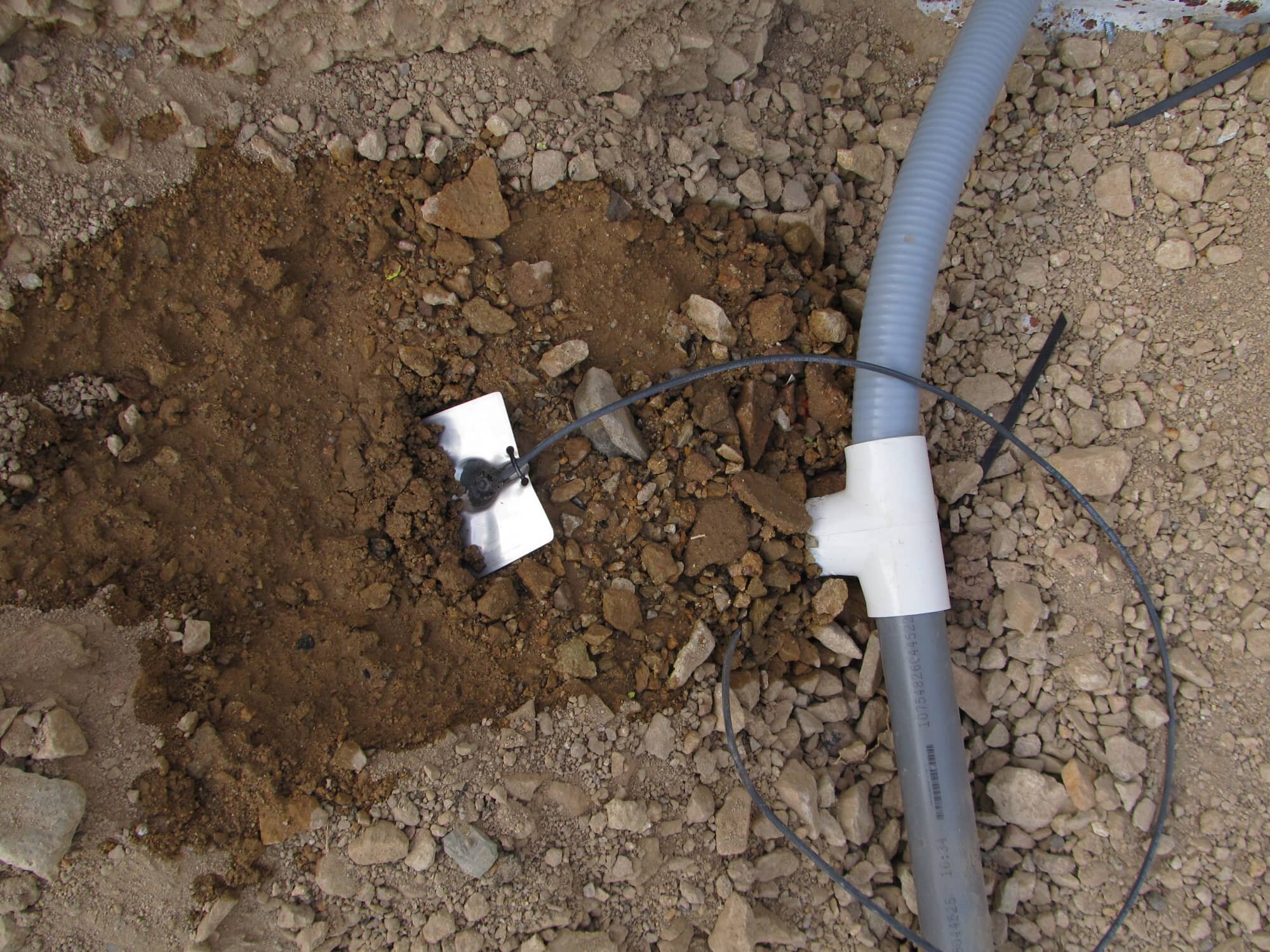
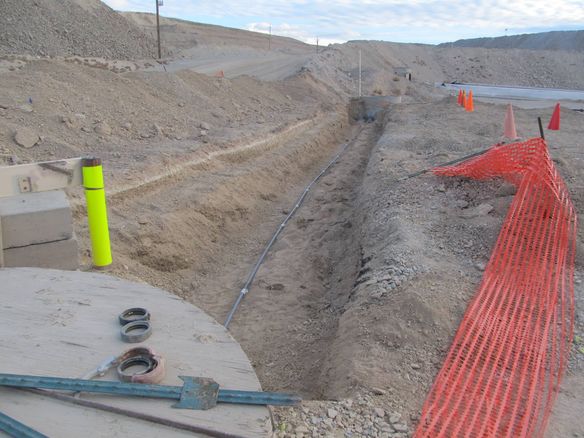
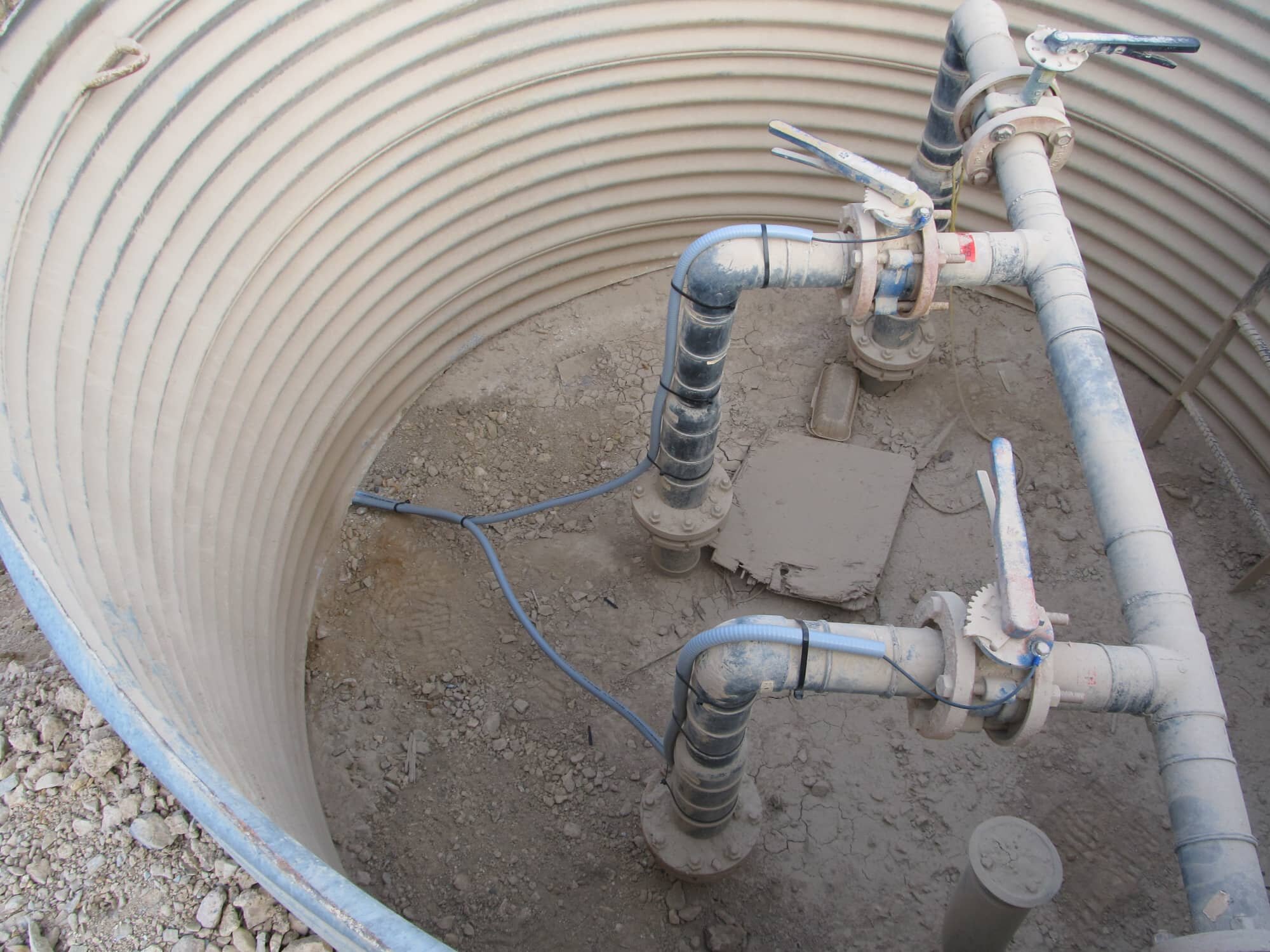
Monitoring nonconductive transfer pipes of liquid may be the best solution for preventing ecological disasters and financial casualties. Pipes installed under roads, concrete, buildings, or permenant structures may undergo environmental loading conditions that may jeopardize the integrity of the pipe. The PELM® System for nonconductive buried pipes was developed to minimize financial and economical damages when a pipe has been damaged. This consists of installing potential electrodes along the surface of the pipes with equidistant spacing. Once all the elements of the PELM® System has been installed, calibration of the system is performed, training is provided, and a final PELM® Survey is conducted. The PELM® System for nonconductive pipes can monitor the life of the application at various frequencies per Client requirements.
X-Linear Coordinate System
1-Dimensional Linear Configuration
installation of wires and electrodes
soil depth of 3 in (8 cm)
* PELM® is a registered trademark of Beyond Leak Detection